Do you have a question about the Controls J1939 and is the answer not in the manual?
Configuration of engine throttle type, speed, and ramp rate settings for optimal operation.
Configuration of J1939 CAN bus communication parameters like source and engine addresses.
Procedure for starting the engine using the control panel's key switch.
Procedure for stopping the engine using the control panel's key switch.
Manual and Hydro throttle control methods for adjusting engine speed via panel buttons.
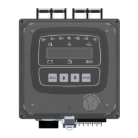
Details of the 14-pin primary connector, including its mating connector and wire entry side.
Details of the 23-pin secondary connector, including its mating connector and wire entry side.
Lists pin assignments and functions for the 14-pin primary connector.
Lists pin assignments and functions for the 23-pin secondary connector.
Details the 21-pin Deutsch engine harness connector and its pin assignments.
Overview of the customer connection terminal strip for external inputs/outputs.
Explains how engine ECU actions like de-rating or shutdown are managed based on operating parameters.
Describes how the panel displays trouble codes, descriptions, and occurrence counts from the ECU.
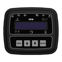
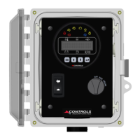
Description of the six indicator lamps on the control panel and their functions.
How to view active and stored ECU fault codes via menu options.
Details of panel-specific alarms like fuel level, oil pressure, temperature, and battery voltage alarms with ranges and delays.
Configuration and default settings for Analog Input 1 (Fuel Level).
Configuration and default settings for Digital Inputs 1-4 (Hydro Throttle, Override, E-Stop, Low Water).
Describes wiring and function of a digital hydro throttle switch on terminal strip position 1.
Describes wiring and function of a digital emergency stop switch on terminal strip position 2.
Describes wiring and function of an analog fuel level sender on terminal strip position 3.
Describes wiring and function of a digital low water level switch on terminal strip position 4.
Explanation of 'Off / Always / Run' monitoring modes for digital inputs.
Definition of 'Alarm Delay' for digital functions, specifying the time before an alarm is latched.
Default settings for Relays 1-8, including function, polarity, and initial state.
Detailed descriptions of available relay functions like Pre Alarm, Alarm, Engine Run, and specific alarms.
Explanation of 'Positive' (Normally Open) and 'Invert' (Normally Closed) relay polarity settings.
Options for relay initial state: 'On' (activated upon power up) or 'Off' (not activated).
Overview of emissions data displayed by the panel, including DPF load and regeneration status.
Explanation of how the engine ECU controls regeneration based on emissions parameters.
Describes the levels of severity for regeneration and corresponding indicator lamp behavior.
Details the operator prompts and confirmations required for a standard regeneration process.
Explains the illumination of the Regen Active Lamp and DPF Lamp during the regeneration process.
Describes the most severe regeneration level, indicator behavior, and potential engine de-rating.
Explains methods to inhibit regeneration, including answering "No" to prompts and using the "Inhibit Regen" setting.
Instructions on how to enter, navigate, and exit the menu system using panel buttons.
Steps for changing settings within the menu system, including using brackets and confirmation.
Lists of main menus for viewing engine parameters, emissions, events, and identification.
Lists of password-protected setup menus for configuring various engine and panel functions.
Covers Quick, Engine Parameter, Input, Output, and Throttle configurations.
Engine Safety, Module, Display, and CAN configurations.
Auto Shutdown, Maintenance, Emissions, and Modbus configurations.
Detailed settings for clutch engagement and release parameters.
| Brand | Controls |
|---|---|
| Model | J1939 |
| Category | Control Panel |
| Language | English |