Coopra Advanced Heating Technologies Installation manual E40C
16
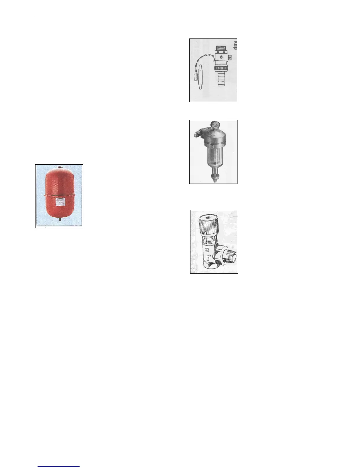
2.2.3. Safety valve and Draconian connection
The boiler has been provided with electronics that block
the burner at a water pressure of 3.5 bar.
When the water pressure rises further the safety valve
will open at a water pressure of 3.7 bar.
The discharge (4) under the boiler should determinate
facing downwards exterior to the building in a position
where discharging water will not create danger or
nuisance but remains in a visible position.
There must be a connection for the removal of the
condensation water to the drain. This connection must be
fitted with a trap to prevent smell problems.
A tundish connection must be made because of possible
overpressure or under pressure in the drain.
Fit the condensation drain pipe (8) (inner diameter 40
mm minimum) several centimeters left of the gas pipe.
2.3. Expansion vessel
In the heating return pipe, as near as to the boiler, an
expansion vessel must be fitted.
The size of the expansion vessel
must be determined on the basis of
the heating water temperature and
the total water content the
installation contains.
Example of Emmeti “Expansion
vessel”
The pre-pressure depends on the installation height
above the mounted expansion vessel.
5 meters - 0,5 bar
10 meters - 1,0 bar
15 meters - 1,5 bar
2.4. Filling and draining device
Install a filling and draining device
in the heating system.
2.5. Dirt filter
If it may be expected that the
heating water will be severely
contaminated by under floor
heating, fitting a 2 kg dirt fine filter
in the return pipe is recommended.
With this, possible contamination of
the heating water is prevented from
ending up in one of the units.
Coopra cannot give any guarantee
for damage to the unit that is
caused by dirt in the system.
Example of PermaTrade “dirt filter” type PT-FM-25W
2.6. Differential bypass valve
A differential bypass valve must be
installed on plants where it may
happen that various heating units
(radiators) are simultaneously
excluded from the circuit because
of the closure of control or zone
valves. It ensures a recirculation
proportional to the number of shut
off valves, thus avoiding noise and
keeping the pump pressure steady.
Example of Caleffi “Bypass valve” type 519500 (¾”)
Mounting: The differential by-pass valve must be
mounted in the installation between the flow and the
return piping. It may be mounted both horizontally and
vertically, provided that flow direction indicated by arrow
is respected.
Adjustment: Rotate knob on the desired value of the
graduated scale. The values correspond to the meters of
pump head (m H2O). The advised knob setting is 2.5-
3.0. Lock the screw on the groove knob.
 Loading...