Coopra Advanced Heating Technologies Installation manual E40C
27
7.6.4. Check function of gas control
- open the outlet pressure nipple of the gas valve
- connect the pressure gauge to the outlet pressure nipple
- measure the outlet pressure (zero)
- start heat demand (chimney sweeper function)
- first, the fan will pre-purge at 1800 rpm
- next, the fan runs at the ignition speed of 2900 rpm.
- now, the pressure gauge will indicate an under pressure
of approximately 3 mbar
- the same moment the gas valve opens, the zero
governor makes zero gas pressure.
- if not, then the gas control is not functioning.
7.6.5. Check glow plug (no ignition)
BE CAREFUL !!!
230 VAC
The 230 volt glow plug is in order if the measured
resistance at room temperature is about 1.0 - 1.4 kOhm.
Replacing the glow plug
The glow plug is a resistance through which current is fed.
As a result of the high temperature of the glow plug, the
burner can be ignited. This makes the glow plug a part
that wears. The average life of the glow plug is estimated
at 8 years, depending on the number of starts and on the
variation of the mains voltage.
• remove plug from glow plug (230 V high voltage)
• remove glow plug from cover of heating unit
• replace glow plug
7.6.6. Check the fan impedance
Check the resistance of the
coil, the two outermost
contacts on the fan motor.
The value that the multimeter
shows must be between 115
and 120 Ohms at room
temperature.
7.6.7. Gas/air mixture is not correctly adjusted
See the chapter concerning the adjustment full load and
low load.
7.6.8. Inspection ionisation probe/cleaning
Unplug the plug of the
ionisation probe (low voltage).
Remove the two screws from the ionisation clamp.
Remove the ionisation probe from the lid of the heating
unit.
Check the ionisation probe.
The ionisation probe must be straight and clean (a slight
deposit is normal).
Clean or replace the ionisation probe.
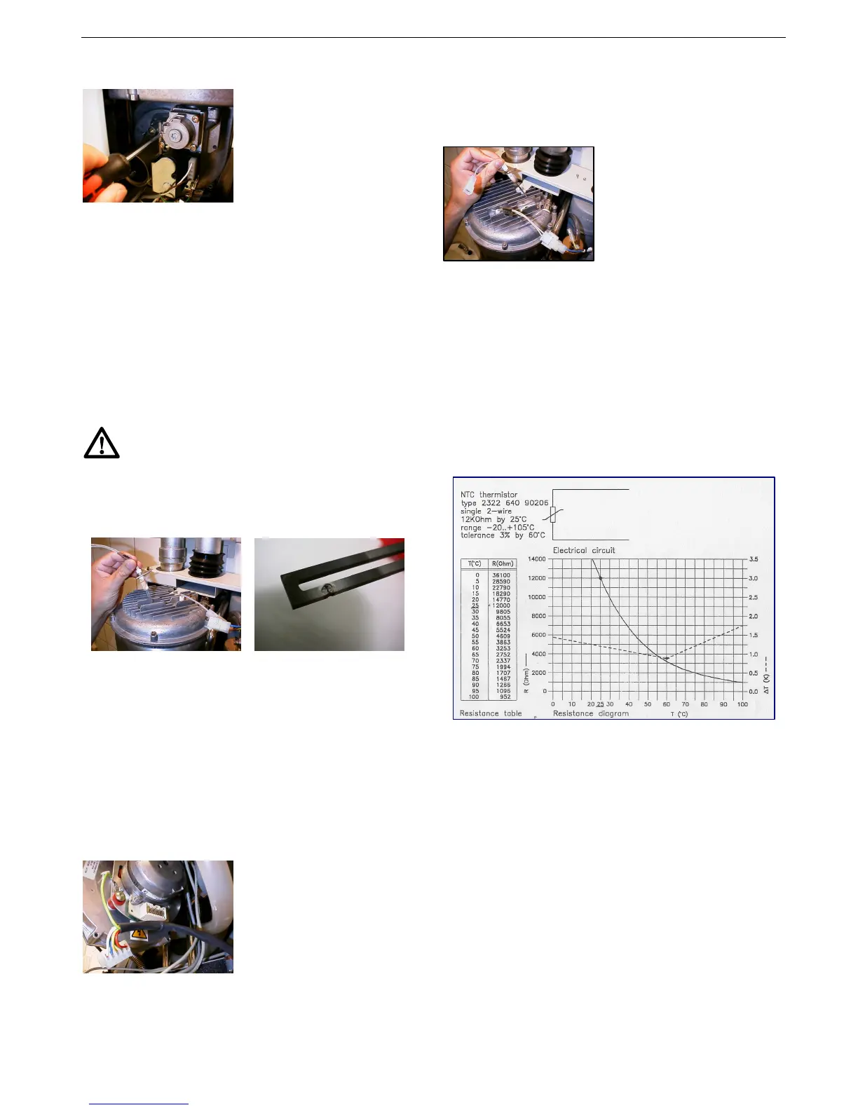
7.6.9. Temperature sensors
The temperature sensors are NTC thermistors of 12kOhm
(@ ambient of 25‘C).
 Loading...