NOTE: Be very careful when removing the welding nozzle. The contact tip on this welder is live
whenever the torch trigger is pulled. Make certain power is turned OFF.
5. INSTALL THE WIRE - We recommend the usage of .023, .030 & .035 MIG wire, or .030 and
.035 flux core wire, on this unit.
5.1 Select welding wire - Both four-inch or eight-inch wire spools of .023, .030, or .035
wire can be used on this welder.
NOTE: Burn-through can occur if you attempt to weld mild or stainless steel thinner than 24
gauge.
NOTE: Remove all rusted wire from your wire spool. If the whole spool is rusty, discard it.
5.2 Installing the wire.
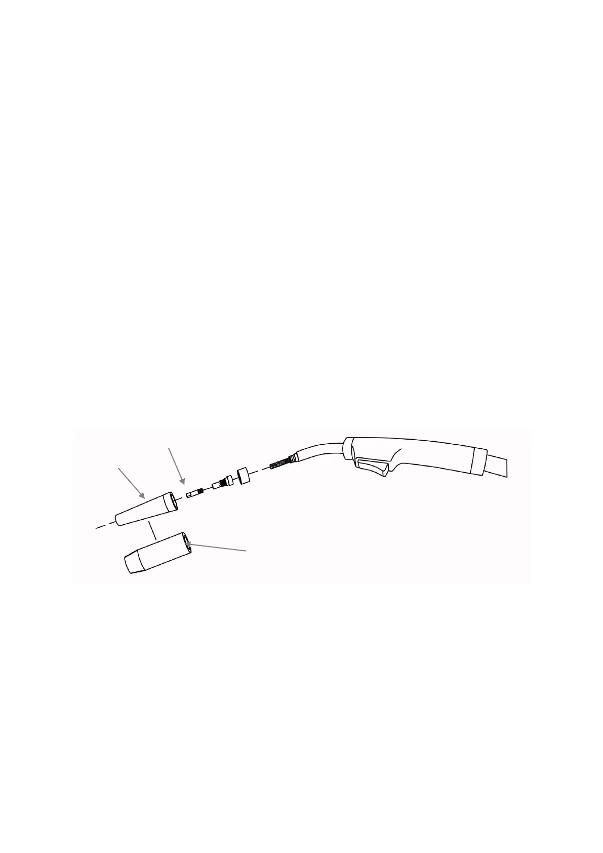
5.2.1 Remove the nozzle and contact tip from the end of the torch assembly.
See Figure 3.
5.2.2 Make sure the proper groove on the drive roller is in place for the wire
installed. If not, change the drive roller as described in INSTALL THE
WIRE ROLLER above.
5.2.3 Remove the packaging from the spool of wire and then identify the
leading end of the wire secured on the edge of the spool. DO NOT
UNHOOK IT AT THIS TIME.
Figure 3
5.2.4 Place the spool on the spool hub so the wire will pull off the bottom of
the spool. The welding wire should always come off the bottom of the
spool into the drive mechanism (Figure 4).
 Loading...