Installation 5
6.
Risk of electric shock. Can
shock, burn or kill.
Go to a dry area, remove wet shoes and
change wet clothing. WHEN YOU ARE DRY,
plug the extension cord into a grounded
electrical outlet (with a GFCI, if possible).
DO NOT STAND IN WATER TO PLUG IN
THEPUMP.
7. National Electrical Code (NEC) and Canadian
Electrical Code (CEC) requirements prohibit the
use of an extension cord with this pump in a
permanent installation.
As soon as possible, remove the extension
cord and reinstall the pump as a permanent
replacement pump whose power cord
connects directly into a properly grounded
grounding-type receptacle. Install the pump
in accordance with the instructions, and in
accordance with all codes and ordinances
thatapply.
8. Monitor the pump’s operation. The pump will
automatically stop when the water level has
receded to the OFF point of the switch.
NOTICE CSA has not approved the use of an
extension cord with this pump.
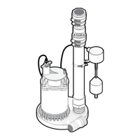
Installation
1. Install pump in sump pit with minimum
diameter of 10” (254mm). Sump depth should
be 10” (254mm). Construct sump pit of tile,
concrete, steel or plastic. Check local codes for
approved materials and for proper installation.
2. Install pump in pit so that switch operating
mechanism has maximum possible clearance.
Switch Setting in inches (mm)
On Off
8” (203) 3.5” (89)
3. Pump should not be installed on clay, earth or
sand surfaces. Clean sump pit of small stones
and gravel which could clog pump. Keep
pump inlet screen clear.
NOTICE Do not use ordinary pipe joint
compound on plastic pipe. Pipe joint
compound can attack plastics.
Risk of flooding. Can cause
personal injury and/or property damage.
If a flexible discharge hose is used, make
sure pump is secured in sump to prevent
movement. Failure to secure pump may allow
pump movement, switch interference and
prevent pump from starting or stopping.
4. Power Supply: Pump is designed for 115 V.,
60 Hz., operation and requires a minimum
15amp individual branch circuit. Both pump
and switch are supplied with 3-wire cord sets
with grounding-type plugs. Switch plug is
inserted directly into outlet and pump plug
inserts into opposite end of switch plug.
Risk of electric shock. Can
shock, burn or kill.
Pump should always be
electrically grounded to a suitable electrical
ground such as a grounded water pipe or a
properly grounded metallic raceway, or ground
wire system. Do not cut off round ground pin.
5. If pump discharge line is exposed to outside
sub-freezing atmosphere, portion of line
exposed must be installed so any water
remaining in pipe will drain to the outfall
by gravity. Failure to do this can cause water
trapped in discharge to freeze which could
result in damage to pump.
6. After piping, check valve and float switch have
been installed, the unit is ready for operation.
7. Check the pump operation by filling sump with
water and observing pump operation through
one complete cycle.
Risk of flooding. Can cause
personal injury and/or property damage.
Failure to make this operational check may
lead to improper operation, premature failure,
and flooding.