Installation • Operation 5
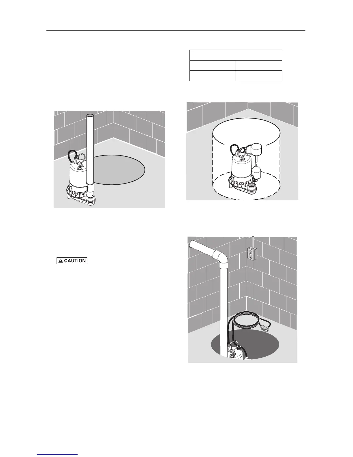
4. Install a check valve in the vertical pipe (see
Figure 2) to prevent flow backwards through
the pump when it shuts off. To prevent
airlocking the pump, drill a 1/8” (3.2 mm)
hole in the discharge pipe just above where
it screws into the pump discharge. Install the
check valve above this hole, but keep it as
close to the pump as possible. Be sure the
hole is below the waterline and below the
checkvalve.
5. To reduce motor noise and vibrations, a
short length of rubber hose (1-7/8” (47.6mm)
I.D., e.g. radiator hose) can be connected
into discharge line near pump using
suitableclamps.
Risk of flooding. Can cause
personal injury and/or property damage.
If a flexible discharge hose is used, make
sure pump is secured in sump to prevent
movement. Failure to secure pump may allow
pump movement, switch interference and
prevent pump from starting or stopping.
6. The switch is set to operate at these settings:
Switch Setting in inches (mm)
On Off
7.5” (190) 3” (76)
7. Placethepumpinthesump;makesurethat
nothing interferes with switch operation.
8. Finish installing the necessary plumbing.
Follow the glue manufacturer’s instructions for
safety precautions and curing time.