1 0
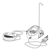
Internal Irrigation Nozzle
Drill
Irrigation Tube
5-7 Compatibility check of Internal Irrigation Nozzle/Drill
Internal irrigation nozzles accompanied with this product; is not necessarily fitted into all the drills on the
market. Follow the instructions given below for confirmation prior to use.Failure to do so or to fit the internal
irrigation nozzle into drills may cause a leakage of saline solution, which will result in problems such as rust or
sudden stop of equipment during use.
Instructions:
(1) Attach a bottle of saline solution to the Control Unit.
(2) Connect the Internal Irrigation Nozzle into the tip of the irrigation tube.
(3) Insert the Internal Irrigation Nozzle into the drill from the back.(Fig. 11)
(4) Purge at “Maximum” for 5 seconds.
If malfunction such as a leakage of saline solution from the back of Contra Head is detected during use, stop using and perform
some troubleshooting.
CAUTION
5-8 Irrigation Nozzle Attachment
C6-9/C6-19 has 1 irrigation method available depending on tool and application; External, Internal or both,
For installation detail, refer to the handpiece Operation Manual.
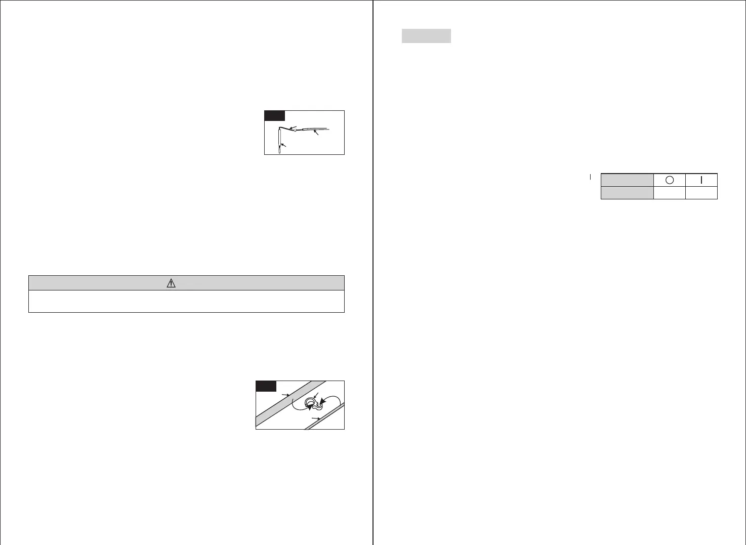
5-9 Attaching the Tube Holder
Use the Motor Cord as a strain relief for the 'Irrigation Tube'. It is
easier to insert Motor Cord first, then the Irrigation Tube.(Fig. 12)
Points to be checked :
◇ Cleanliness of the saline solution coming out from the drill; if solution is colored there could be rust inside
of the drill. If so renew the drill.
◇ Water Flow; if the flow is low and/or the flow from the drill is asymmetric, renew the drill.
◇ No water leakage between Internal Irrigation Nozzle and drill.
Before use, ensure no water is leaking from the entry point of irrigation nozzle, a broken seal or no seal in
the drill.may be the cause. Replace the drill even if its new, saline solution ingress into handpiece will
cause malfunction.
9
6-1 Programming the Micromotor Operation
The Control Unit can memorize . Each program includes the following functions which will be
automatically performed when the appropriate program number is selected.
Gear ratio of contra angle handpieces
Speed
Direction of rotation
Torque upper limit
Coolant Solution Flow
10 programs
◇
◇
◇
◇
◇
6. Operation
Fig. 11
ON
Power Switch
Symbol Mark
FUNCTION
OFF
(1) Turn on the power by pushing the Main Power Switch toward [ ];
on power up program #1 is displayed by default.
(2) Select a program number by using either step (a) or step (b):
(a) Press the [Program] Key on the Control Panel until the desired program number is displayed.
(b) Press the [Program] button on the Foot Control until the desired program number is displayed.
(3) Selecting the Gear Ratio of the handpiece relevant to the program; Press the [Gear Ratio] Key to select the
gear ratio of the handpiece(Gear Ratio will display on the LCD).
(4) Set the required max operating speed by pressing the [Speed] Key. Each time this Key is pressed display
changes to the next speed level. By pressing this Key for more than 1 second brings the speed quickly to the
next level until the speed display reaches its upper or lower limit.
- When the speed setting reaches the upper or the lower limit, an audible beep is heard and the speed setting
cannot be changed any further.
(5) Set the torque upper limit by pressing the [Torque] Key on the Control Panel. Each time this Key is pressed
display changes to the next torque level. By pressing this Key for more than 1 second brings the torque
quickly to the next level until the torque display reaches its upper or lower limit.
- When the torque setting reaches the upper or the lower limit, an audible beep is heard and the torque
setting cannot be changed any further.
(6) Set the rate of the Coolant Solution Flow volume by pressing the [Coolant Flow] Key. The rate of Coolant
Solution Flow volume has 6 Flow rates (0-5) (0 = no coolant Flow).
(7) Memorize setting; after completing steps 2 - 6 press and hold [Memorize] key until beep is heard. The beep
confirms that the programming is completed. If you hear a short beep when the [Memorize] Key is first
pressed ignore this sound and keep the [Memorize] Key depressed until a long beep is heard.
* Repeat the above steps 2 - 7 to program any one of the 10 available programs.
Motor Cord
Tube Holder
Irrigation Tube
Fig. 12
Fig. 11
 Loading...