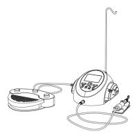
The COXO C-Sailor Dental Implant Motor System is a Class I medical device with a Type B applied part, designed for use in dental oral surgery and surgical procedures by qualified personnel. It operates in an intermittent mode (ON 2 min/OFF 10 min) to prevent overheating. The system is protected against the effects of 30 minutes' immersion in water (Foot Control: IPX7).
Function Description:
The C-Sailor system facilitates dental implant procedures by providing precise control over a micromotor and handpiece. It allows for programming of various operational parameters, including gear ratio, speed, direction of rotation, torque upper limit, and coolant solution flow. The system is designed to address indications such as missing teeth, mandibular alveolar absorption, and difficulties with traditional dentures.
Important Technical Specifications:
Control Unit:
- Model: C-Sailor
- Power Supply Voltage: AC230V
- Frequency: 50Hz
- Power Consumption: 120VA
- Max. Pump Output: 100mL/min
- Dimensions: W285 x D265 x H155mm
- Operating Temperature: 0-40°C (32-104°F)
- Operating Humidity: 10-85%RH
- Operating Atmospheric Pressure: 700-1060hPa
Micromotor:
- Speed Range: 300-50,000r/min
- Input Voltage: DC30V
- Dimensions: Ø27 x L123mm
- Code length: 1.77m
- Ingress Protection: IPX7
Handpiece (Purchased separately):
- Models: C6-9, C6-19
- Max. Rotation Speed: 2,500r/min
- Gear Ratio: 20:1 Reduction
- Spray Type: External, Internal* (if internal irrigation system drills are used)
- Compatibility: Fits ISO 3964 20:1 and IEC 80601-2-60 Standard requirement Implant contra angle
- Torque: More than 55 N.cm (Do not exceed the bur manufacturer's recommended rotation speed. Adjust rotation speed if allowable speed is less than 120,000r/min-1.)
Infusion Tube:
- Purchased separately (REF 04363600).
Cooling Liquid:
- Physiological saline (Internal and external cooling) (concentration: 0.9%; flow velocity: 0-100 ML/min).
Usage Features:
Control Unit Interface:
The Control Unit features a clear LCD display showing:
- Coolant Flow Level (0-5 levels, 0 = off)
- Program Number (1-10)
- Gear Ratio
- Forward/Reverse Indicator
- Speed (rpm)
- Torque (N.cm)
- Pedal Link Indicator
Key buttons on the Control Unit include:
- Program Key: Cycles through available programs (ascend/descend).
- Speed Key: Adjusts micromotor speed (increase/decrease). Audible beep at limits.
- Torque Key: Sets torque range (increase/decrease). Audible beep at limits. Torque is not displayed for 1:1 direct drive or speed increasing handpieces.
- Gear Ratio Key: Sets the gear ratio of the attached handpiece.
- Coolant Flow Key: Selects 6 levels of coolant solution flow (0-5).
- FWD-REV Key: Changes rotational direction of the micromotor. Audible beep in reverse mode.
- Memorize Key: Saves programmed parameters. A long beep confirms memorization.
The Foot Control provides hands-free operation with:
- Coolant Solution Flow Volume Button: Selects 6 levels of coolant flow.
- PRG (Program) Button: Selects desired program number (ascends sequentially).
- Speed Control Pedal: Starts/stops the micromotor and controls speed proportionally to pedal position, up to the preset maximum.
- Forward/Reverse Button: Changes micromotor rotational direction.
Programming Micromotor Operation:
The Control Unit can store 10 programs, each encompassing gear ratio, speed, direction, torque limit, and coolant flow.
- Turn on the Main Power Switch. Program #1 is displayed by default.
- Select a program number using the [Program] Key on the Control Panel or the [Program] button on the Foot Control.
- Set the handpiece gear ratio using the [Gear Ratio] Key.
- Set the maximum operating speed using the [Speed] Key.
- Set the torque upper limit using the [Torque] Key.
- Set the coolant solution flow volume using the [Coolant Flow] Key.
- Memorize settings by pressing and holding the [Memorize] Key until a long beep is heard.
- Turn on the Main Power Switch.
- Select the program number using the Foot Control PRG button.
- Verify program details on the display.
- Operate the micromotor by stepping on the speed control pedal. Coolant pump runs if programmed. Speed increases with pedal depression.
- Torque limiter activates if drilling load reaches the preset torque limit, stopping the motor after a 1-second beep. Release and depress the pedal to reactivate.
- Release the speed control pedal to stop the micromotor.
- Change rotational direction using the Foot Control Forward/Reverse button.
Installation:
- Motor Cord: Plug into the main unit and fasten the fixed nut.
- Foot Control: Insert plug into connector socket and secure with lock nut.
- AC Electrical Cord: Align and insert into connection socket at the back of the Control Unit.
- Irrigation Tube: Install water supply pipe, send needle side of clamp ring alignment host back in, and guide the load. Ensure tube is securely set on rollers before closing the pump cover to prevent cutting/shearing.
- Coolant Solution Hanger Post: Mount onto the holder on the Control Unit (supports up to 2 kg).
- Irrigation Tube Insertion: Close tube clamp, insert needle into bottle cap, open tube cap for air, and open tube clamp. Do not operate pump if tube is bent or clamp is closed, as this may cause bursting or slipping.
Compatibility Check (Internal Irrigation Nozzle/Drill):
Verify that the internal irrigation nozzle fits the drill to prevent saline solution leakage, which can lead to rust or equipment malfunction. Check for cleanliness of saline solution from the drill, water flow, and water leakage.
Maintenance Features:
Protection Circuit:
An electronic circuit breaker protects the micromotor and Control Unit from overload, displaying an error code. To reset, release and depress the Speed Control Pedal.
Troubleshooting:
A detailed table is provided for diagnosing and remedying common malfunctions, including system malfunction, over current/voltage, motor sensor malfunction, main unit overheat, braking device malfunction, motor running malfunction, water supply pump issues, and foot control abnormalities.
Fuse Replacement:
If the Control Unit malfunctions, check the fuses located on the rear. Use a pointed tool to push the locking latch and open the drawer. Internal fuse replacement requires disassembling the host.
Maintenance of Control Unit and Foot Control:
Wipe with a damp cloth and alcohol-absorbed cloth if stained with blood or saline solution. Disconnect power supply before cleaning. These components cannot be sterilized.
Maintenance of Handpiece Attachment:
- After each treatment, place the handpiece head in clean water and rotate for 4-5 seconds to clean blood and physiological saline.
- Wipe excessive attachments with a dry, soft rag. Do not immerse the entire handpiece in water.
- Lubrication (after use, before high-temperature/high-pressure sterilization): Insert the nozzle into the handpiece behind and spray for more than 2 seconds. Hold handpiece tight during lubrication. Shake the tank for oil and gas to mix. Clean the lubrication oil tank.
- If the handpiece head is heavily soiled, clean and refuel separately. Install a clean nozzle and wash from inside.
- Clean a stuck water supply nozzle with a needle.
- Clean dirt around the nozzle with a brush.
Cleaning, Disinfection, Packing, and Sterilization:
Manual Cleaning:
- Use softened water (< 38 °C) and a brush to clean surfaces of motor and line until visually clean.
- Clean crevices and cavities, especially on the E-type connector screw, gap parts, and motor rear part. Remove liquid remnants with an absorbent cloth.
Manual Disinfection:
Use KaVo Cavicide disinfectant liquid.
Packing:
- Use sterilization packaging that complies with standards and is suitable for the procedure.
- Cover potentially infectious areas with sterile disposable products.
- Seal the handpiece tray and motor cable in a sterilization pouch.
Sterilization:
- Autoclave sterilization is recommended for first-time use and after each patient.
- Autoclave sterilization holding time: 15 minutes at 121 °C.
- Attach the Autoclave Plug to the Micromotor.
- Place items in an autoclave pouch (not included).
- Autoclavable items: Implant Handpiece, Micromotor with Motor Cord (including Motor Housing), Handpiece Stand, Internal Irrigation Nozzle, Tube Holder, Nozzle Holder, Autoclave Plug, Calibration Bur.
Warranty:
The main unit and foot pedals have a 12-month warranty; the motor has a 6-month warranty. Other accessories are not included. Circuit diagrams, component lists, descriptions, and calibration instructions can be provided upon request.
Disposal:
Consult the dealer for waste disposal methods.
Symbols:
- CE0197: EU directive 93/42/EEC compliance.
- IPX7: Protected against 30 minutes' immersion in water.
- Waste Disposal Symbol: Dispose of device and accessories via approved methods for electronic devices and in compliance with Directive 2002/96/CE.
- Type B Applied Part
- This Way Up
- Fragile, Handle with Care
- Foot Pedal Connector
- See Operation Manual
- Used Indoor Only
- Keep Away from Rain
- Warning
- ON (Power Connection)
- OFF (Power Disconnection)
- Alternating Current
- Electric Fuse
- EC REP: European Union Agent
- CE Mark
- Date of Manufacture
- Manufacturers