REARRAIL
(SIDEVlBt/)
POST
FRONtRAIL
(SIDEVIEW)
,2-?
Fig.4
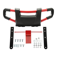
GUIDE FENCE ASSEMBLY
• Liflthe blade guardand placethe dpfence against
the sew bladeand lockthe dpfence in place. This
willinsurethatthe ripfence remainssquarewhile
installingthe mountingbars.
• Slide mountingbare into fronttrack on dpfence
and move themto the center of the fence.
• Positionshimssothat the mar edges are flush
withthe rear edge ofthe fence and the slotsline
upwith the twoholes in each mountingbar.
SI Postition the two guideblockassembliessothat
the rearedges are flushwiththe rear edge of the
fence and the two slotsline upwith the slotsin
the shims.
• Assemble 1/4 in, flat wasbars onto each knob
bolt and screw knob bolts into holes on mounting
KNOBBOLT
bars as showninFigure5.
RiPFENCE
SHIM
GUIDEFENCE
ASSEMBLY
Fig,5
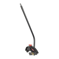
INSTALL GUARD/DUST COVER
• Slidethe head of one of the 1/4 x 3/4 in. boltsinto
the mar trackon the guidefenceand the other
intothe front track.
SI Feed boltsthroughholes in post,Place a 1/4 in.
fiatwasher and lockwasher on each boltand
securewith 1/4 in. hex nutsusingan adjustable
wrench. See Figure 6.
SUDEHEN)OFHEXBOLTINTO
TRACKSONRIPFENCE Fig.6
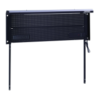
• Loosenthe knob onthe guard/dustcoverby
turningthe knobcounterclockwise.Loosenthe
knobenough so that the post slips easilythrough
the hole in the rear oftheguard/dust cover,
• Positionguard/dustcover so that itis over the
throatof the muter table and approximately3-1/4
in.fromthe table surface.See F/gum 7.
• Secure guard/dustcoverby turningthe tension
knobclockwise,Do not oved:ightan,
Note: The topopeningof the Guard/DustCover
functionsas an ako(illimydustportandwillfitdust
collectiondeviceswitha 2 in.diameter hose.
5
INSTALL ROUTER
SI Unplug the muter.
Fig. 7
,_k WARNING: Unplugthe routerto avoidpos-
sibleinjury.
SI Place your muter upsidedown on a workbech.
SI Removethe subbasescrewsand the subbase
fromyourmuter. Note:The subheseis mounted
permanentJyon some mutere and shouldnotbe
removed.
• Selectthe screwsneededfor yourparticularmuter.
Forconsumerreuters,usethe 114o20screws.For
commercial routere,use the5/16-18 screws.
• Positionmuter upsidedown underthe muter
extensiontable.The muter label shouldbe facing
the frontof the table.