Page 16 of 62
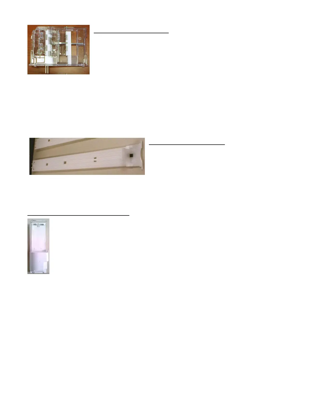
DOUBLE GATE ASSEMBLY (Can/Bottle Trays)
The Double Gate assembly is mounted on the front portion of the Tray assembly and
contains the Vending Mechanism. Incorporated in the Gate assembly are the front
and rear knuckle assemblies as well as the product kicker. In standby operation, the
front knuckle is in the blocking position, which holds the front Displayed product in
position to be vended. The rear knuckle assembly is in a flat position, which allows
product to enter the Gate area, and the kicker is flush to the rear knuckle assembly.
A stainless steel pin is inserted through the rear most portion of the front knuckle assembly and connects to a
gear box below the Tray. When a selection is made, the plunger pushes the lever toward the back of the Tray. At
the same time the front knuckle is opened into a flat position, the rear knuckle is closed to a blocking position,
holding the remaining product out of the Gate area, and the kicker is extended to firmly push the front Displayed
product off of the Tray. The plunger is energized for approximately 1-½ seconds to allow ample time for the
Displayed product to be ejected from the Shelf. The plunger is then released and the front knuckle returns to the
blocking position, the rear knuckle and kicker return to their standby position and the next product slides into the
vend Display position.
SLIDE/PUSHER ASSEMBLY (Can/Bottle Trays)
The Slide/Pusher assembly is located on the bottom of each
product column. Its purpose is to provide a slick, friction
resistant surface for the product to rest on. A tall Product
Pusher is mounted on the top of the Slide and incorporates
a coil spring in the body that attaches to the bottom of the Slide through a slit. This spring adds needed tension
to insure that all products in the column remain tight against each other and are allowed to progress into the Gate
area. Periodic cleaning and lubrication of the slides is recommended. DO NOT USE SOLVENTS OR ABRASIVE
MATERIALS TO CLEAN ANY PORTION OF THE TRAY.
DELIVERY (PICKER) CUP ASSEMBLY
The Delivery (Picker) Cup assembly is located on the XY Vend Mechanism. Its purpose is to pick the
product from the column and deliver the product to the Delivery Port assembly. The Delivery (Picker)
Cup assembly is mounted on the Y Axis Assembly of the XY assembly and bolts in position. The New Y
Home Magnetic Switch located on the bottom of the Delivery Cup has been implemented to eliminate
moving parts that exist on mechanical switch to improve performance. It eliminates the previous
mechanical Switch and the Home Switch Errors caused by syrup and/or dirt build up in/on the
mechanical Switch and Switch arm. The Delivery Cup Brushless Motor, Picker/Plunger Home & Out
Switches, and product detection Sensor are driven by the independent Cabinet Control Cup Board.
 Loading...