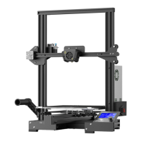
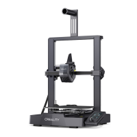
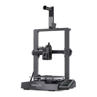
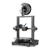
From the underside of the (02) Printer Base, insert 2x M5x45
hex socket cap screws through the predrilled holes on the left
of the frame, so the thread is sticking out through the top face
of the aluminium profile
Identify each of the Z-axis vertical profiles to be used in this
step: (15) Z-axis vertical profile left (2040) and (16) Z-axis
vertical profile right (2040). While they may look the same there
are subtle differences:
The (15) left vertical profile can be Identified as having two
threaded holes, one next to the other, positioned close to the
end. The end with these two holes is the base of the upright and
will be attached to the (02) Printer base;
The (16) right vertical profile features two threaded holes, one
on-top of the other. Positioning of these screw holes are not
symmetrical, with the hole closest to the end of the profile
being the bottom hole. This end, with the screw hole closest to
the end, is the base of the upright and will be attached to the
(02) Printer base.
 Loading...
