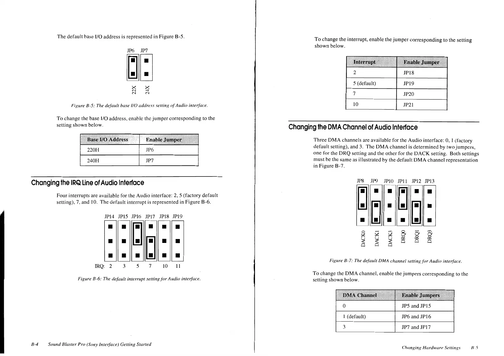
The
default
base
I/O
address
is
represented
in
Figure
B-5.
JP6 JP?
~~
Figure B-5: The default base
110
address setting <!(Audio interf{u:e.
To
change
the
base
1/0
address.
enable
the
jumper
corresponding
to the
setting
shown
below.
elfO
Address
220H
JP6
240H
JP7
Changing
the
IRQ
Line
of
Audio
Interface
B-4
Four
interrupts
are
available
for the
Audio
interface: 2, 5 (factory
default
setting),
7,
and
I
0.
The
default
interrupt
is
represented
in
Figure
B-6.
JP14 JP15
JP16 JP17
JP18 JP19
•
•
~
•
•
•
• •
~
•
•
• • •
•
•
IRQ: 2 3 5 7
10
11
Figure B-6: The default interrupt setting
for
Audio
interface.
Sound
Blaster Pro (Sony Interface) Getting Started
To
change
the
interrupt,
enable
the
jumper
corresponding
to
the
setting
shown
below.
2
JP18
5 (default)
JP19
7
JP20
10
JP21
Changing
the
OMA
Channel
of
Audio
Interface
Three
DMA
channels
arc
available
for
the
Audio
interface: 0, 1
(factory
default
setting), and 3.
The
OMA
channel
is
determined
by
two
jumpers,
one
for
the
DRQ
setting
and
the
other
for
the
DACK
setting.
Both
settings
must
be
the
same
as
illustrated
by
the
default
OMA
channel
representation
in
Figure
B-
7.
.11'8
JP9 JPlO
JPll
JP12 JPl3
Figure B-7: The default DMA channel settingf(>r
Audio
inter.face.
To
change
the
DMA
channel,
enable
the
jumpers
corresponding
to
the
setting
shown
below.
0 JPS
and
JP15
1 (default)
JP6
and
JPl6
3
JP7 and
JPl7
Changing Hardwar'' Scllings
II
5