The
settings for the parameters in the
command
are
described
below.
Parameter
Axxx
Ix
Dx
Hx
Pxxx
Tx
Description
Specifics
the audio interface's base
1/0
address.
xxx
can
be
220, 240, 260,
or
280.
Specifies
the interrupt
request
line
used
by the
audio
interface.
x
can
be
2, 5, 7,
or
JO.
Specifics
the Low
OMA
channel used by the
audio
interface. x can be 0,
I,
or
3.
Specifics the High
OMA
channel used by the
audio
in
terrace.
x
can be
5,
6.
or
7.
Spcci
fies the
MPU-401 interface's
base
1/0
address.
xxx
can he
300
or
330.
Specifies the card type.
x
must he
6.
MIDI
Environment
Variable
C-2
The
MIDI
environment
variable specifics the MIDI
file
format used and
where
the
MIDI
data
is
sent
to.
The
MIDI
data
can be sent to
PM
chips
or
MIDI port.
Generally,
there are three MIDI file formats
available
in
the market,
General
MIDI,
Extended
MIDI and Basic MIDI.
The
command
for setting
the
MIDI
environment
variable
is
as follows:
SET
MIDI=SYNTH:x
MAP:x
The
parameters
of
the
command
are
described
below.
Parameter
SYNTH
MAP
Description
x
can
he
I
or
2.
If it
is
I,
the internal
synthesizer
is
specified. If it
is
2, the
MIDI
port is specified.
The
factory dcfau
It
for x is
1 .
x
can
be
G, E,
or
B.
If
it is
G,
the
General
MIDI
file
format
is specified.
If
it is E, the
Extended
MIDI
file
format is specified.
Ifit
is
8,
the Basic MIDI
file
format is specified.
The
factory
default for
xis
E.
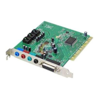
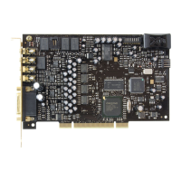
Sound
Blaster
Pro
(Sony
Interface)
GettinK
Started
D
A
Closer
Look
at
Your
Internal
Device
Connectors
You may want to internally
connect
your
audio
card
to
other
devices
on
your
system (such as
another
audio card),
or
simply
redirect
the
"beeps"
that you hear from
your
system to
your
external speakers.
This
section
will
define
the pins
of
each internal
connector
on
your
audio
card. It will
also
show
you how to redirect the
PC
sounds
to
your
external
speakers.
£
Read this section only
if
you are
an
advanced
user
who
knows
how
~to
use the pin assignments.
If
you want to
redirect
sound,
you
should also he
familiar
with your system's
motherboard
and
know
where
to
rind your system's internal speaker.
CD
In
Connector
Pin
Assignments
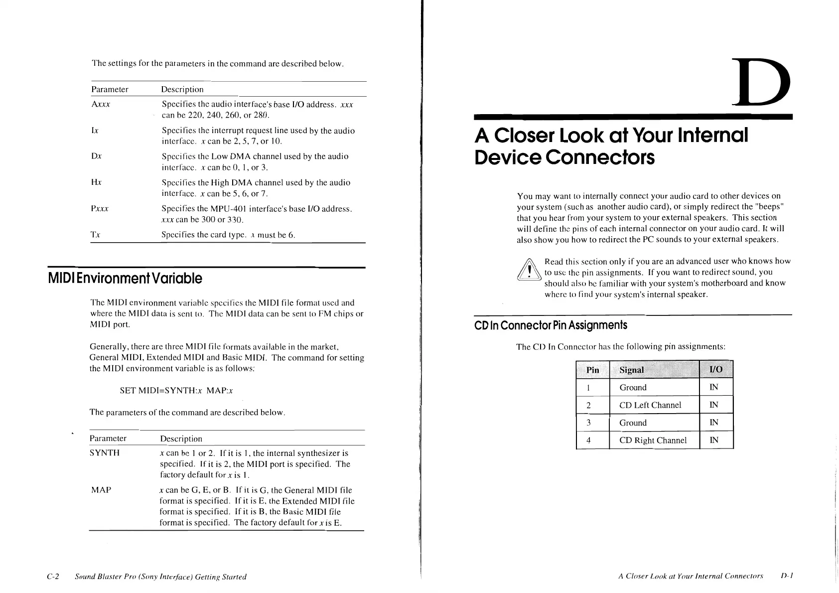
The
CD
In
Connector
has the following pin assignments:
Pin
Ground
IN
2
CD
Left Channel
IN
3
Ground
IN
4
CD
Right Channel
IN
A
Closer
Look
at
Your Internal
Connecrors
I>-
I