Crestron AV2 & PRO2 2-Series Integrated Dual Bus Control System
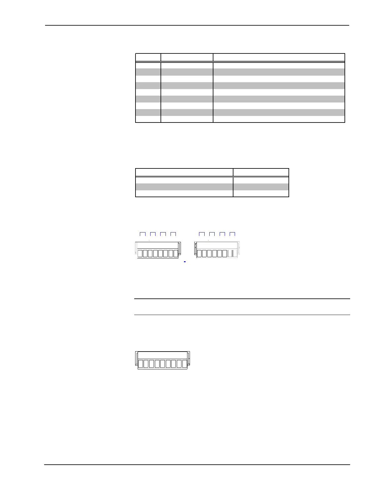
Non-Standard COM Pinout
PIN DIRECTION DESCRIPTION
1* To AV2 or PRO2 (RXD-) RS-422 Receive Data (Idles low)
2 To AV2 or PRO2 (RXD) RS-232 Received Data
3 From AV2 or PRO2 (TXD) RS-232 Transmitted Data
4 From AV2 or PRO2 (TXD+) RS-422 Transmit Data (Idles high)
5 RS-232 and RS-422 Signal Common
6 To AV2 or PRO2 (RXD+) RS-422 Receive Data (Idles high)
7 From AV2 or PRO2 (RTS) RS-232 Request to Send
8 To AV2 or PRO2 (CTS) RS-232 Clear to Send
9 From AV2 or PRO2 (TXD-) RS-422 Transmit Data (Idles low)
Where: *= RS-422 transmit and receive are balanced signals requiring two lines plus a ground in each
direction. RXD+ and TXD+ should idle high (going low at start of data transmission). RXD-
and TXD- should idle low (going high at start of data transmission). If necessary, RXD+/RXD-
and TXD+/TXD- may be swapped to maintain correct signal levels.
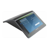
COM Pinout to RS-485 Bus
COM (DB9) CONNECTOR RS-485 BUS
Tie Pins 1 & 9 -
Tie Pins 4 & 6 +
Pin 5 G
INFRARED – SERIAL OUTPUT
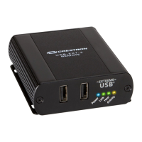
Infrared – Serial Output Connectors
S5
INFRARED
SERIAL
OUTPUT
A
B
C
D
E
F
G
H
S
G
S
G
S
G
S
G
S
G
S
G
S
G
S
G
On the rear panel there are eight serial outputs for IR or serial interface. Each output
is labeled S (signal) and G (ground). Infrared output is rated up to 1.2 MHz. Serial
protocols include one-way RS-232.
NOTE: RS-232 levels on the infrared – serial output connectors provide a 0 – 5V
range, which may not be compatible with all devices.
I/O
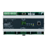
I/O Connector
S6
I/O
1
2
3
4
5
6
7
8
G
On the rear panel there are eight software programmable analog and digital inputs as
well as digital outputs. Digital outputs offer 250mA sync from maximum 24 VDC;
catch diodes for use with "real world" loads. Digital inputs are rated 0 – 24 VDC,
20K ohms input impedance, logic threshold 1.25 VDC. Analog inputs are rated 0 –
10 VDC, protected to 24 VDC maximum, 20K ohms input impedance; pin-
programmable 2K ohms pullup resistor to +5V.
Operations Guide - DOC. 5957 Integrated Dual Bus Control System: PRO2 & AV2 • 5