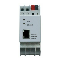
KNX Control Interface Crestron CI-KNX
18
KNX Control Interface: Crestron CI-KNX Operations & Installation Guide – DOC. 0008
Every change of the input signal will result in a string being sent out. It uses the
lower 8 bits of the analog signal. The value of the input signal should therefore range
between 0 and 255. The analog input signal can be generated by an Analog Initialize
symbol (see above).
Also the output signal ranges from 0 to 255 (low byte).
Data type 2 Byte
The 2 byte data type is almost identical to the 1 Byte data type. In this case however
the value to be controlled and read out is 16 bit (0d to 65535d). 2Byte modules are
mostly used to read out analog values like temperature.
The module also offers inputs and outputs to use the EIS type. EIS5 is a KNX data
type that is commonly used to send a 2 Byte decimal value to the KNX system.
E.g. Set the “Set_EIS5_Value” input to 2550 to send 25,5 to the KNX system.
Values to set the correct temperature (1800d, 2200d) depend on the KNX device.
Data type 4 Byte
The 4 byte module is almost identical to the “Crestron CI-KNX 2 Byte v1.6”
module. In this case however the value to be controlled and read out is 32 bit (0d to
4294967295d). SMPL windows only supports 16 bit analog signals so the 32 bit
value is split into two 16 bit signals. These signals represent the 16 high and low bits.
The module also offers a signed and unsigned and Floating Point serial outputs to
display the 4 Byte value.