3-Series Control Systems Crestron CP3 & CP3N
10 • 3-Series Control Systems: CP3 & CP3N Operations Guide – DOC. 7316C
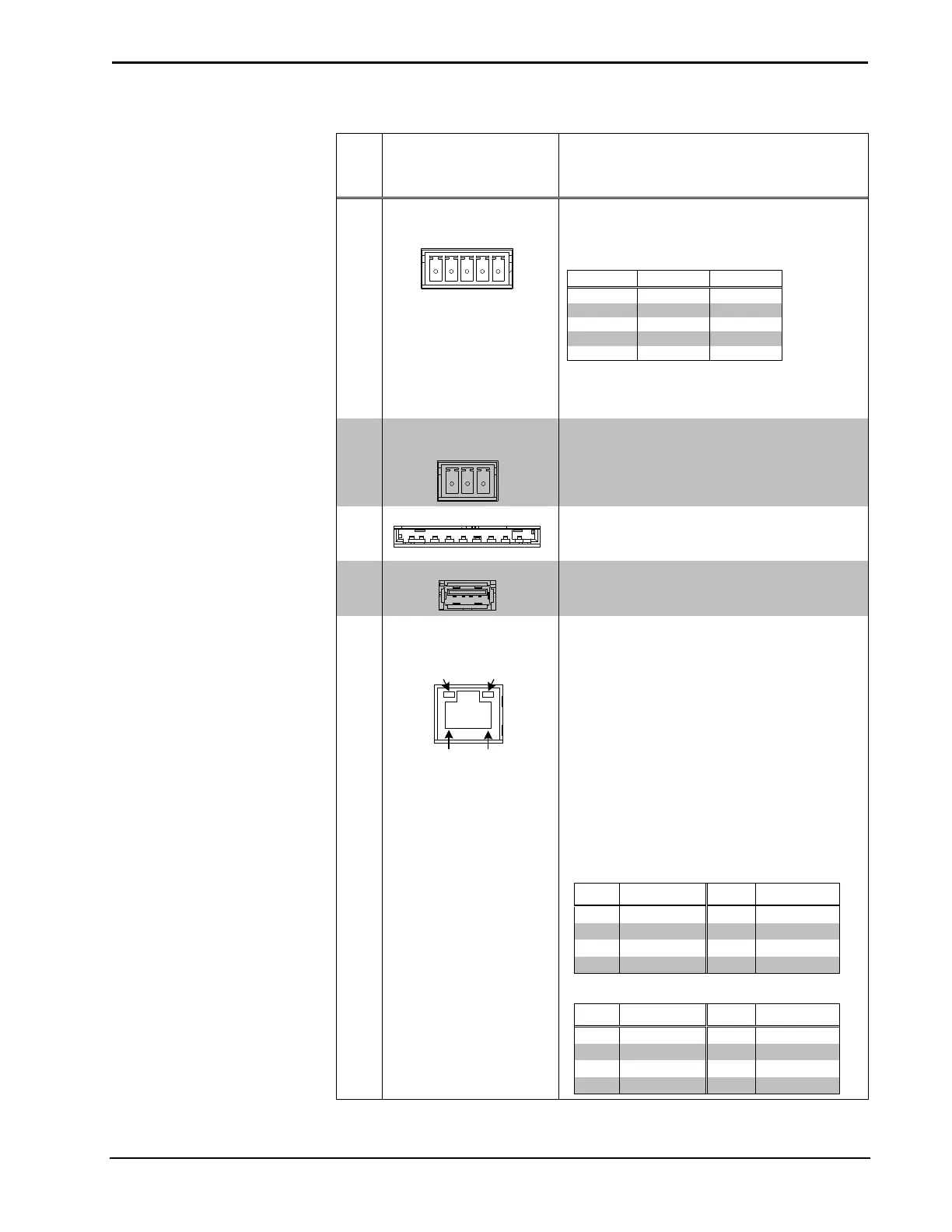
Connectors, Controls & Indicators (Continued)
# CONNECTORS*,
CONTROLS &
INDICATORS
DESCRIPTION
9 COM1
(1) 5-pin 3.5 mm detachable terminal block
Bidirectional RS-232/422/485 port
Up to 115.2k baud;
hardware and software handshaking support
* A ground terminal connection is recommended
but not required. Ground potential difference
10 COM 2 & COM 3
(2) 3-pin 3.5 mm detachable terminal blocks;
Bidirectional RS-232 ports;
Up to 115.2k baud;
software handshaking support
11 MEMORY
(1) Memory card slot;
Accepts up to 32 GB for memory expansion
(SD memory card not included)
12 USB
(1) USB Type A female;
USB 2.0 port for storage devices
13 LAN
Amber/
Green
LED
Amber
LED
Pin 8
Pin 1
(1) 8-pin RJ-45 with two LED indicators;
10BASE-T/100BASE-TX Ethernet port (CP3)
(10/100/1000BASE-T Ethernet port (CP3N);
Left LED indicates link status;
Amber: Link – 1 Gbps (CP3N Only)
Green: Link – 100 Mbps
Off: No link or Link – 10 Mbps
Right LED indicates Ethernet activity
Flashing: Activity – Flash rate depends
on amount of activity
Off: No Activity
Connects to the customer’s LAN
CP3 Pin Assignments
CP3N Pin Assignments
(Continued on following page)