2.10
Pinto BT-POM 1212 - Revision 5
Pre-Operation
Hook-up
Assembly Instructions
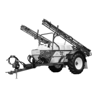
The Pinto is supplied fully assembled with
up to six items requiring assembly after
shipping from the factory:
1 Adjustments to the hitch and PTO
may be necessary to match tractor
drawbar & PTO requirements.
2 Connect the Pinto hitch and PTO
shaft to the tractor (see page 2.10).
3 Connect the Pinto hydraulic hoses to
the tractor (see page 2.12) &/or
electric in-cab control for wing-lift
(optional).
4 Connect and fi t the
• Standard Electric Controller (see
page 2.15),
• Optional MT3405 Controller (see
page 2.16)
5 Connect and fi t the Foam Marker
Controller (optional) to the Tractor.
(See instruction 4 “Fit Foam Marker
Control [Optional]) (see page 2.17).
6 Connect hydraulic pump drive hoses
& adjust (if fi tted as an option for
centrifugal or diaphragm pumps).
1 Adjust the Pinto Hitch
Tongue & Hitch
The Pinto hitch tongue and hitch can be
height adjusted to match your tractor PTO
and drawbar.
To adjust the height of the hitch tongue:
a) Loosen and remove the bolts holding
the hitch tongue.
b) Move/rotate the tongue to the desired
position.
c) Refi t the tighten the hitch tongue
bolts.
To adjust the height of the hitch:
a) Use a jack to support the front of the
Pinto chassis and then, remove the
hitch height adjustment bolt.
b) Raise or lower the Pinto chassis
using the support jack until the correct
height is reached.
c) Replace and tighten the hitch height
adjustment bolt. If removed, refi t the
pump hose.
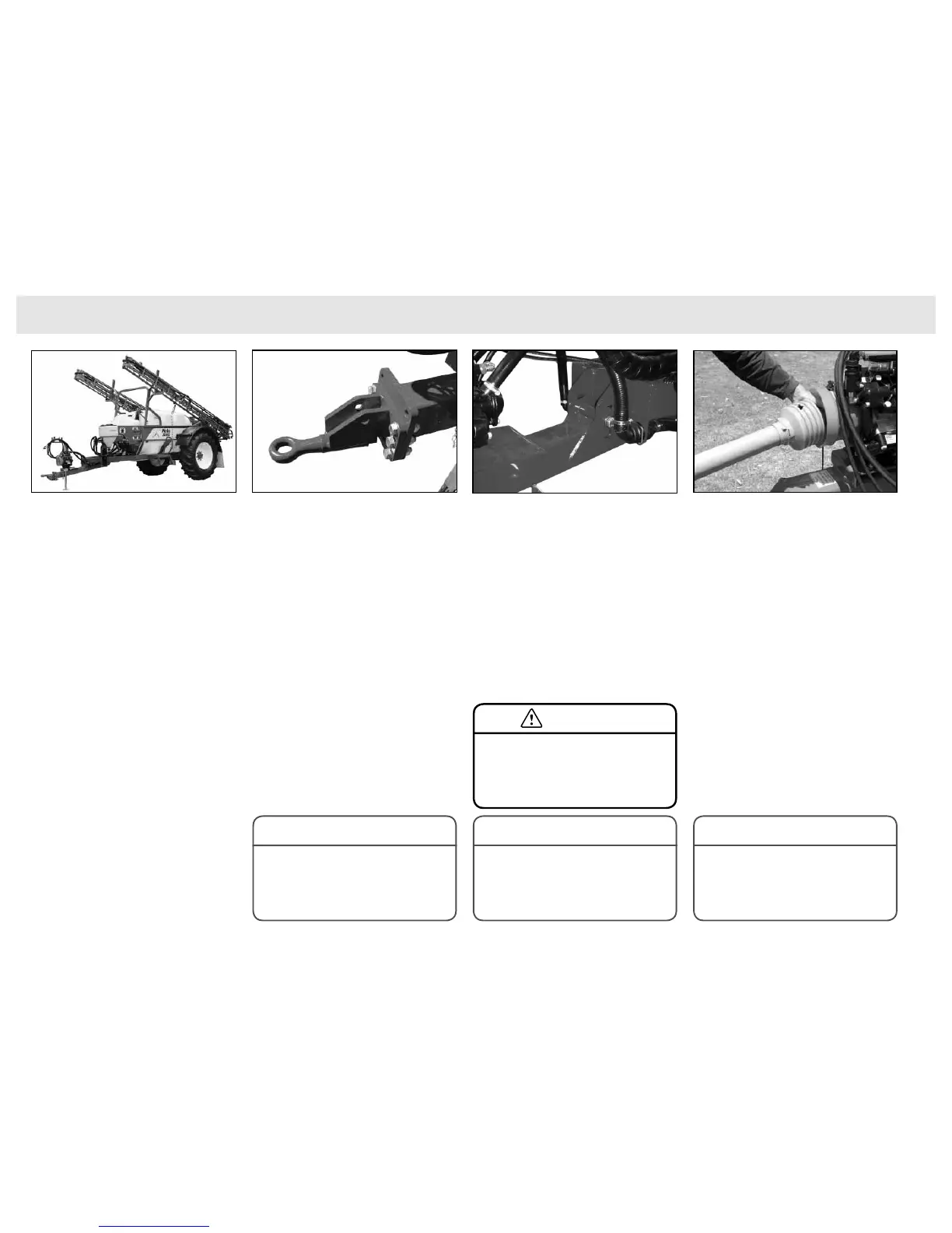
2 Connect the Pinto Hitch
& PTO Shaft to the Tractor
The Pinto must be connected to a suitable
tractor, making sure the drawbar hitch
and PTO shaft are fi tted according to the
instructions that follow:
1 Align drawbars of tractor and Pinto,
insert and lock drawbar pin in position
ensuring the drawbar pin cannot
come out while transporting or
operating.
2 Remove the jack supporting the Pinto
chassis, and store it on the frame lug
provided.
3 Check the Pinto is level fore and aft.
The sprayer should be slightly lower
at the front. If not adjust the sprayer
drawbars and axle to achieve level
position.
The Pinto is fully assembled at the factory. Connect the PTO shaft to the Pinto.Hitch height adjustment bolt in the centre position.
When connected to your tractor drawbar, the
Pinto should be level or slope slightly downwards
at the front.
NOTE
Incorrect hitching of PTO shaft will result in
excessive pump vibration and damage to the
pump.
NOTE
The hitch tongue in its lowest setting.
IMPORTANT: Do not allow more than 10%
difference in the two halves of drawbar length. If
more than 10% difference occurs, a wide angle
shaft must be used.
NOTE
Ensure the tractor linkage arms are well clear of
the pump on the Pinto drawbar when turning.
If tractor linkage arms are not removed or
adjusted to clear the pump when turning then
damage to the pump may occur.
CAUTION