page 9
CE2000TX Power Amplifier
Operation Manual
3.6 Wire Your System
3.6.1 Stereo Mode
Make sure the amplifier is turned off and the
level controls are turned down before you wire
the system.
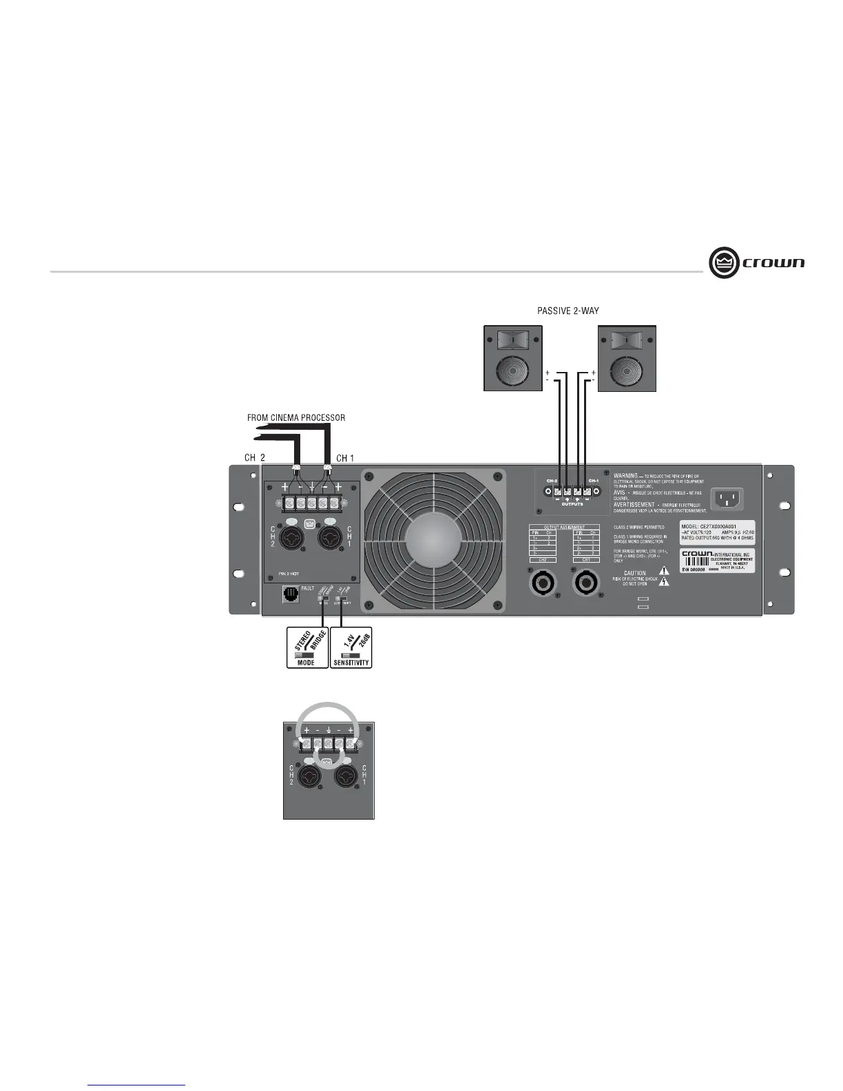
Typical input and output wiring is shown in
Figure 3.9.
INPUTS: Connect input wiring for each channel.
OUTPUTS: Maintain proper polarity (+/-) on out-
put connectors.
Connect Channel 1 positive (+) speaker load to
Channel 1 positive terminal of amp; repeat for
negative (-). Repeat each channel wiring as for
Channel 1. Refer to Section 3.5 for output con-
nector pin assignments. Make sure the Mode
switch is set to the “Stereo” position when oper-
ating in Stereo mode.
How to Parallel the Inputs in Stereo Mode
There are three ways to feed the same signal to
each amplifier channel:
1. Buy a "Y" cable. Plug the female end into your
signal cable, and plug the split male ends into
both amplifier inputs.
2. Feed your signal to the Channel-1 input
(either barrier-block or Combo). Connect a
jumper wire (Figure 3.10) between the barrier-
block Channel-1 (+) screw terminal and the
Channel-2 (+) screw terminal. Connect another
jumper wire between the Channel-1 (–) screw
terminal and the Channel-2 (–) screw terminal.
3. Feed your signal to the Channel-1 input screw
terminals. Using a mic cable or phone-to-phone
cable, connect Channel-1 Combo jack to Chan-
nel-2 Combo jack.
See the next page for Bridge-Mono wiring.
3 Setup
Figure 3.9 Typical System Wiring, Stereo Mode
Figure 3.10 Placement of Jumpers to Parallel the Inputs
SHOWN WITH OPTIONAL CEAS1 OUTPUT MODULE