page 17
CTs Power Amplifiers
Operation Manual
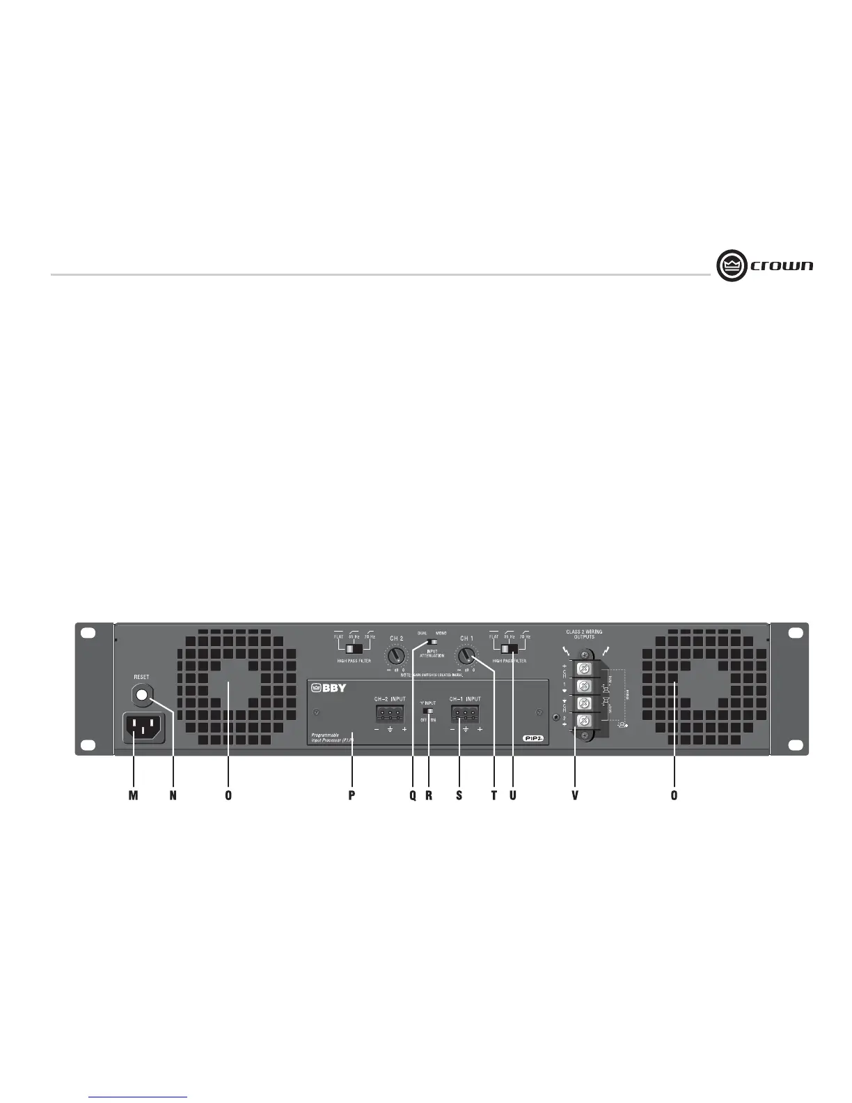
4.3 Back Panel Controls
and Connectors.
CTs 2000/3000 back panel is shown.
CTs 600/1200 look slightly different near
the Reset button.
M. Power Cord Connector
Standard 15 amp IEC inlet. A circuit
breaker located near the IEC power inlet
protects the amplifier from excessive AC
current draw.
N. Reset Switch
Resets the circuit breaker that protects the
power supply.
O. Ventilation Grille
Air flow is front to back. Do not block the
ventilation grilles.
P. PIP ™ Input Panel
PIP2-BBY module includes two balanced
3-pin removable barrier connectors. The
“Y” Input Switch is described under
letter R.
Sensitivity Switches
Behind the input panel are the Input Sensi-
tivity Switches. One 3-position switch per
channel selects various sensitivity set-
tings. See Section 5.2.4 for details and
diagram.
Q. Mode Switch
This two-position switch is used to select
the amplifier’s mode of operation: Dual or
Bridge Mono.
Dual mode is used for 2/4/8 ohms, for 70V
operation with the CTs 600/1200, and for
70/100V operation with the CTs 2000/
3000.
Bridge mode is used for 4/8/16 ohms, for
140V operation with the CTs 600/1200,
and for 100/140/200V operation with the
CTs 2000/3000.
R. “Y” Input Switch
When set to ON, this switch parallels the
input signals of the two channels, for use
when the input signal is mono. The ampli-
fier’s channel outputs are still independent.
The “Y” Input Switch also can be used to
daisy-chain the signal to another amplifier.
See Section 3.6.5 for details.
S. Input Connectors
Balanced 3-pin terminal block connectors,
one per channel.
T. Channel Level Controls
One 21-position detented rotary attenuator
per channel, ranging from –100 dB to 0 dB
gain.
U. High-Pass Filter
One 3-position switch per channel selects
between OFF, 35Hz and 70Hz 3rd-order fil-
ters.
V. Speaker Connectors
One four-pole touch-proof terminal strip.
Accepts up to 10 AWG terminal forks.
Output Cover (not shown)
This covers the output connectors, pro-
tecting users from the connectors’ poten-
tially high voltage. This cover is required
for Class 2 wiring installations. See Sec-
tion 3.5 for details on removing covers that
have two holes.
4 Operation
Figure 4.2 CTs 2000 and 3000 Back Panel Controls and Connectors

 Loading...