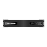
Page 32
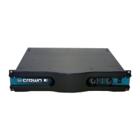
K-Series Balanced Current Amplifier™
“Y” Input: An on/off switch located on the back panel between
the input connectors which, when turned on, parallels the two
input channels.
Indicators
TLC: A TLC (thermal level control) LED for each channel which
turns on with a dim glow shortly before the amplifier needs
help dissipating heat. (See Pg. 21.)
Clip: An orange LED for each channel which turns on when
distortion of any type becomes audible in the amplifier output.
(See Pg. 21.)
IOC:
A yellow LED for each channel which serves as a distor-
tion indicator. The
IOC
indicators include a pulse-stretching
feature that helps make them more noticeable even with rapid
transient signals. (See Pg. 22.)
Signal: A green LED for each channel which flashes dimly
when a very low-level signal (as low as 10 mW) is present in
the output. They flash brightly when a louder signal (at least 1
watt) is present at the output.
Enable: A green LED that turns on when the amplifier has been
turned on and has power. When first turned on, there will be a
brief two-second delay while the amplifier performs a quick
turn-on diagnostic. Then the Enable indicator will turn on to its
full brightness. If no signal is present, the Enable indicator will
switch to a dim level.
Input/Output (Spaghetti Control)
Input Connectors: One balanced ¼-inch phone jack and one
3-pin female XLR connector for each channel.
Input Stage: Input is electronically balanced and employs pre-
cision 1% resistors.
Input Impedance: Nominally 20 K ohms, balanced. Nominally
10 K ohms, unbalanced.
Input Sensitivity: 1.4 volts for standard 1 kHz power, or 26 dB
gain.
 Loading...