EasyManua.ls Logo

Crown K-Series User Manual

Crown K-Series
42 pages
To Next Page IconTo Next Page
Page #1 background imageLoading...
Page #1 background image
102010-2
2/98
KK
KK
K
-Series-Series
-Series-Series
-Series
© 1998 by Crown International, Inc., P.O. Box 1000,
Elkhart, IN 46515-1000 U.S.A. Telephone: 219-294-8000.
Fax: 219-294-8329. Trademark Notice:
Balanced Current
Amplifier
,
and
BCA
are trademarks and
Crown
®
is a
registered trademark
of Crown International, Inc. Other
trademarks are the property of their respective owners.
®
120 VAC North
American
Units Only:
Commercial
Audio
E106377
Lightning Bolt Symbol:
This symbol is used to alert the
user to the presence of danger-
ous voltages and the possible
risk of electric shock.
Exclamation Mark Symbol:
This symbol is used to alert the
user to make special note of im-
portant operating or mainte-
nance instructions found in the
reference manual.
Watch for these symbols:
Question and Answer IconNeed help?

Do you have a question about the Crown K-Series and is the answer not in the manual?

Crown K-Series Specifications

General IconGeneral
BrandCrown
ModelK-Series
CategoryAmplifier
LanguageEnglish

Summary

Safety and Operation Tips

Safety and Operating Instructions

Emphasizes reading and following all safety and operating instructions carefully before use.

Service Assistance Guidelines

Details conditions under which to seek professional service assistance for the amplifier.

Placement and Thermal Warnings

Advises on equipment placement and warns about amplifier heat during heavy use.

Unpacking and Compliance

FCC Compliance Notice

Details the equipment's compliance with FCC rules for Class A digital devices and potential interference.

K-Series Amplifier Features

Quick Start Guide

1 Welcome

Amplifier Layout Overview

2 Detailed Installation Procedures

Mounting and Rack Installation

Details the process of mounting the K-Series amplifier in a standard 19-inch equipment rack.

Mono Modes and Input Sensitivity Configuration

Explains mono mode switches and input sensitivity settings for optimal configuration.

Wiring and Hookup Diagrams

Illustrates various input/output wiring configurations including stereo and mono hookups.

3 Amplifier Operation

Front Panel Indicators and Controls

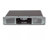
Explains front panel indicators (TLC, Clip, IOC, Signal, Enable) and controls (Level, Power).

Back Panel Functions and Settings

Details back panel controls like input connectors, mono modes, and input sensitivity settings.

Power-Up Sequence and Output Adjustment

Guides the correct power-up sequence and adjusting output levels for desired loudness.

4 Other Issues: Cooling and Heat Management

Amplifier Cooling and Heat Management

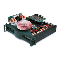
Explains the fanless cooling design, TLC indicators, and managing heat in high ambient temperatures.

Balancing the Line and Noise Troubleshooting

Balanced vs. Unbalanced Wiring

Explains the principles of balanced and unbalanced audio circuits and their noise rejection properties.

Hum and Buzz Troubleshooting Tips

Offers tips for identifying and resolving hum and buzz issues related to grounding and wiring.

5 Specifications

Performance Metrics

Details frequency response, power output, signal-to-noise ratio, and damping factor.

Controls, Inputs, and Outputs

Describes front/back panel controls, input/output connectors, impedance, and sensitivity.

Construction and Physical Attributes

Materials and Finish

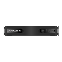
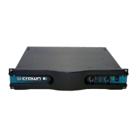
Details the cast-aluminum front panel, Lexan labels, and aluminum chassis with black finish.

Cooling System and Dimensions

Describes the passive convection cooling, rack dimensions, and unit depth.

Amplifier Weight

Provides the weight specifications for the K1 and K2 amplifier models.

6 Service and Warranty Information

Obtaining Service

Explains how to obtain service for the amplifier through authorized centers or factory service.

Warranty Terms and Conditions

Summarizes the three-year full warranty terms, exclusions, and how to obtain service.

Related product manuals