page 9
Macro-Tech MA-3600VZ Power Amplifier
Operation Manual
3.6 Wire Your System
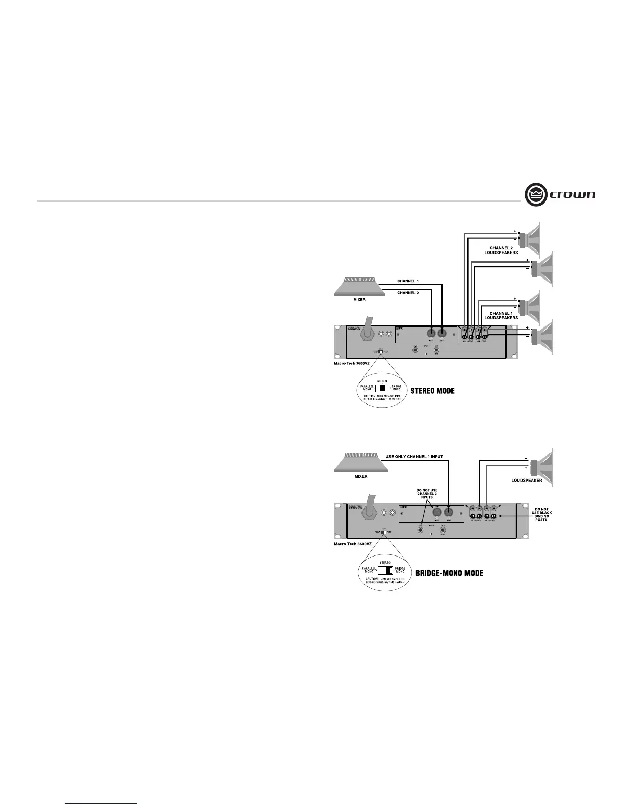
3.6.1 Stereo Mode
Typical input and output wiring is shown in
Figure 3.6.
INPUTS: Connect input wiring for each channel.
Refer to Section 3.4 for input connector pin
assignments.
OUTPUTS: Maintain proper polarity (+/-) on
output connectors.
Connect positive (+) speaker lead to Channel 1
positive binding post of amp; connect negative
(–) speaker lead to Channel 1 negative binding
post of amp. Repeat for Channel 2. Refer to
Section 3.5 for output connector pin assign-
ments. Make sure the Mode switch set to the
“Stereo” position when operating in Stereo
mode.
3.6.2 Bridge-Mono Mode
Typical input and output wiring is shown in
Figure 3.7.
INPUTS: Connect input wiring to Channel 1.
Refer to Section 3.4 for input connector pin
assignments.
OUTPUTS: Connect positive (+) speaker lead to
Channel 1 positive binding post of amp; connect
negative (–) speaker lead to Channel 2 positive
binding post of amp. Do not use the negative
binding posts when operating in Bridge-Mono
mode. Refer to Section 3.5 for output connector
pin assignments. Make sure the Mode switch is
set to the “Bridge” position when operating in
Bridge-Mono mode.
NOTE: Turn down (full CCW) the Channel
2 level control when operating in Bridge-
Mono mode, as the Channel 1 level
control works both channels.
3 Setup
Figure 3.6 System Wiring, Stereo Mode
Figure 3.7 System Wiring, Bridge-Mono Mode
 Loading...


