Form I-RA/D 350/500, P/N 131090R12, Page 11
Remote Fuel Pump
The Model OT-250 tank has a platform designed for attaching the remote
fuel pump.
• Attach the fuel pump legs permanently either on the platform,
directly to a eld-supplied tank, or in a location very near to the oil
tank.
• Mount the remote pump assembly in an upright, horizontal
position as shown in the illustration. NOTE: Motor enclosure
appearance may be different than illustrated but must always be
mounted in this upright position.
NOTE: Do not mount the pump assembly in a vertical
or inverted position.
Pump
Supply Lines
Installation
CAUTION: Do not use TEFLON
®
based pipe dope or
TEFLON
®
tape to seal any pipe connections. (TEFLON
®
is a registered trademark of DuPont Chemical.) Use of
TEFLON
®
based pipe dope or TEFLON
®
tape will void
the pump warranty.
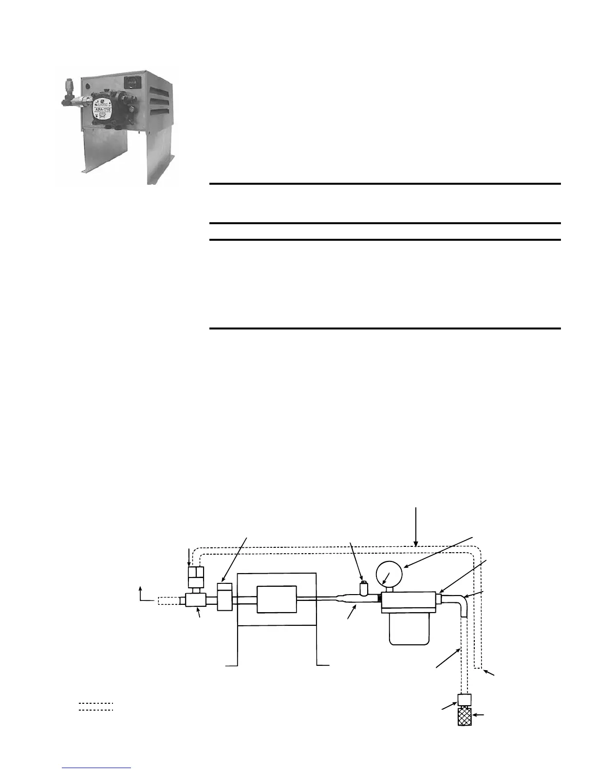
Supply Lines
Read this section carefully before installing any supply lines. Since a suction line leak is nearly impossible
to nd, take your time to assure all connections are leak-free during installation. Supply lines and t-
tings are furnished by the installer. See the following illustration for minimum ttings required. Length
of pipe and tubing depends on the installation.
Run the suction line, using 1/2” standard black iron pipe, between the inlet side of the lter and the foot
valve. (Refer to the illustration.) A fuel line lter with a cleanable strainer, a foot valve, a foot valve strainer,
and a vacuum gauge are provided with the heater. To prevent air from entering the line, do not use union
connections at joints. Install the suction line components as illustrated. With the vacuum gauge mounted