Form I-RA/D 350/500, Page 42
Troubleshooting
Continued
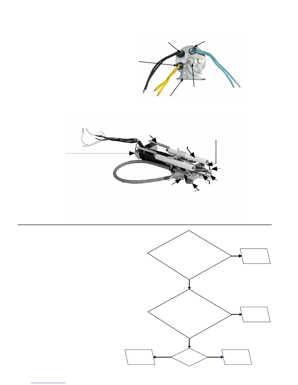
Oil Heat Exchanger and Fuel Line Assembly
Reference Chart No. 1, page 41
Locations and
Replacement
Instructions for
Heating Element and
Temperature Controls
on Oil Pre-heat Heat
Exchanger
Refer to illustrations on
pages 39-40.
Oil Heating Element - To
remove the heating element,
remove retainer/support and
pull heating element forward.
Oil Temperature
Control (blue leads)
Low Oil
Temperature Limit
(black leads)
High Oil
Temperature
Limit Switch
(yellow leads)
Retainer Support
Nozzle Low Oil
Temperature Limit
(black wires)
Electrode
Ceramic
Insulator
Buss Bar
Static Plate
Nozzle Temperature Control (red wires)
Nozzle Adapter
(see below)
Nozzle
Inlet Heater
Remove the silicone rubber to
free heating element (30 watt).
When replacing, use silicone rub-
ber to retain the new element.
The nozzle adapter also contains a 30 watt heating element. To replace the element: 1) Remove the
buss bars and 2) unscrew the inlet heater and slide the black insulation rearward. Loosen set screw
which holds the static plate and slide rearward. This will expose the heating element.
Locations and Replacement Instructions for the Two 30 Watt
Heating Elements in the Fuel Line Assembly
Chart No. 2 - Thermostat calling for
heat, burner motor never attempts
to run (green light is lit) indicating
“System Ready”. Chart No. 1 has
been successfully completed.
NOTE: After ignition control is reset, you will have 30
SECONDS to perform the tests shown below before
the controller locks out.
Reset ignition control:
Press the BUTTON,
hold for four seconds, and release. DO
NOT RESET MORE THAN ONE TIME.
*Reset button on the motor activates
when the motor is overheated. Motor
amp draw must be less than the full
load amps on the motor rating plate.
Verify the motor is operating correctly.
*Is burner
motor reset button
tripped?
Reset and check
for proper
operation.
Replace burner
motor.
Replace fuse
(CSA units).
Replace ignition
controller.
YES
NO
YES
NO
YES NO
Check for 115V
across Terminals 5 and 2.
Is voltage read?
(Above applies to Size 500 mfgd beginning 1/2005.
For a Size 500 mfgd before 1/2005,
check for 115V across
Terminals C and B.)
Check for 115V
across Terminals 13 and 11.
Is voltage read?
(Above applies to Size 500 mfgd beginning 1/2005.
For a Size 500 mfgd before 1/2005,
check for 230V across
Terminals 5 and 2.)