Form I-RA/D 350/500, Page 40
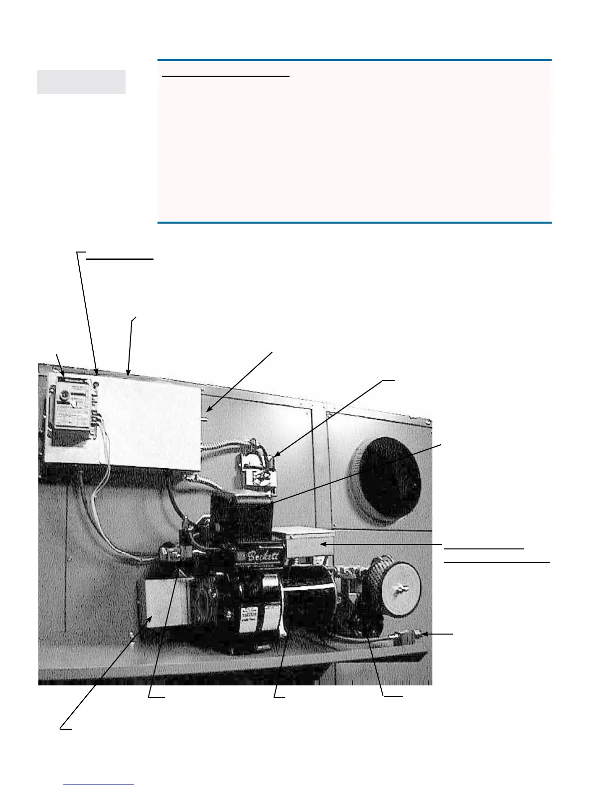
Location of Components Referenced in Troubleshooting Charts
Size 500
Manually reset Backow
Sensor Switch on the
Viewport Door
Transformer (Open
the transformer
to service the cad
cell.)
5 amp fuse
mounted on the
top of the electric
box. See wiring
diagram.
Ignition
Controller
Green Light: Limits
are satised; heater
is ready to operate.
*Air pressure switch is inside the main
electrical box.
220V eld connections are inside the main
electrical box.
Green Indicator Light (”power on”)
Manual Disconnect Switch
Oil Inlet
Connection
115V Terminal
Connections 11-19
are in the burner
junction box.
Piston-type Air
Compressor
Box contains oil heat exchanger (pre-heater) with 770 watt
cartridge heating element and temperature controls.
Burner Motor
Reset Button
*Main
Electrical
Box
Burner Tee
with Strainer
IMPORTANT NOTE: Effective 1/20/2005, Models RA/RAD
500 were converted to a 240 volt 3-wire system. The car-
tridge heaters, air compressor, burner, and hour meter were
changed from 240 volt to 120 volt.
Where applicable, troubleshooting charts have alternate
instructions for a Size 500 manufactured prior to 1/2005.
Before troubleshooting, check the wiring diagram on the
heater against the Size 500 diagrams on pages 50-57 to
verify which instructions apply to the unit being serviced.