Form I-RA/D 350/500, P/N 131090R12, Page 15
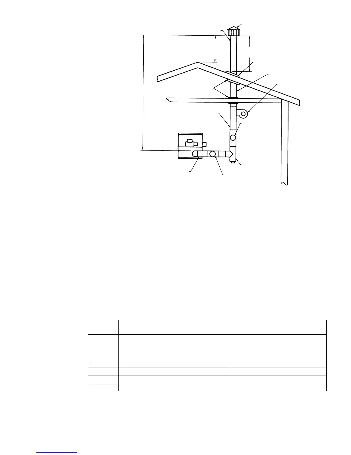
• Any portion of the vent
system that passes
through an unheated
space or a concealed
area such as an “attic”
must be a factory-built
vent that is approved to
Standard UL 641. See
illustration . . . . . . . . . . .
• The heater may be
vented into a masonry
chimney that complies
with the BOCA National
Mechanical Code for
low-heat appliances or
other building code re-
quirements for low-heat
appliances.
Detailed Requirements for the Vent System
• Pipe/Joints/Clearances: Single-wall pipe must be a minimum of 24 gauge
galvanized steel for 8” or 9” diameter pipe and 22 gauge for 10” or 12” diameter
pipe. Each joint must be secured with three screws or rivets. If installing a factory-
built vent, follow the manufacturer’s instructions.
If the vent system passes through a combustible wall, material or roof, for single
wall pipe, maintain 18” (457mm) clearance or install a ventilated thimble that is not
less than 12” larger than the diameter of the vent pipe. If installing factory-built vent,
follow the manufacturer’s instructions.
• Horizontal Length and Slope: The horizontal portion of the vent must comply
with the maximum horizontal length shown in the table below and have not more
than two elbows except where noted that the application is limited to one elbow.
Horizontal portions must be sloped upward 1/4” for each foot of pipe. If installation
conditions require horizontal lengths in excess of those permitted in the table, a draft
inducer must be used.
Vent Pipe
Diameter
Model Size and Vertical Length
Maximum Length of
Horizontal Pipe
8” 350 with 8 feet (2.4M) of vertical pipe 3 feet (.9M) or less and only one elbow
8” 350 with 12 feet (3.7M) of vertical pipe 6 feet (1.8M) or less
8” 350 with 14 feet (4.3M) or more of vertical pipe Equal to or less than the vertical height
10” 350 with 8 feet (2.4M) or more of vertical pipe Equal to or less than the vertical height
10” 500 with 8 feet (2.4M) of vertical pipe 3 feet (.9M) or less and only one elbow
10” 500 with 10 feet (3M) of vertical pipe 5 feet (1.5M) or less
10” 500 with 12 feet (3.7M) or more of vertical pipe Equal to or less than the vertical height
• Vent Size: The vent system must be at least 8” in diameter.
• Barometric Draft Regulator: A barometric draft regulator which is the same
diameter as the vent pipe must be used, and it should be located close to the heater.
See below. Do not install a manual damper or any other device that will obstruct the
free ow of the ue gases.
(read all
before
beginning
installation)