Form I-RA/D 350/500, Page 18
Heating
Thermostat
Pump Power
Power
Installation
DANGER: Make sure that the main circuit is OFF before
making any wiring connections. All wiring must be
done in accordance with appropriate Codes!
To connect the electrical power from the heater to the pump,
• Use a 3 conductor, 14 gauge wire system (RA/RAD 350 - two
115 volt conductors and a ground; RA/RAD 500 - two 230 volt
conductors and a ground). Use BX if permitted, but make certain
to follow local codes for running conduit.
• Refer to the Field Connection Chart on the wiring diagram for
connecting terminals.
Main Power
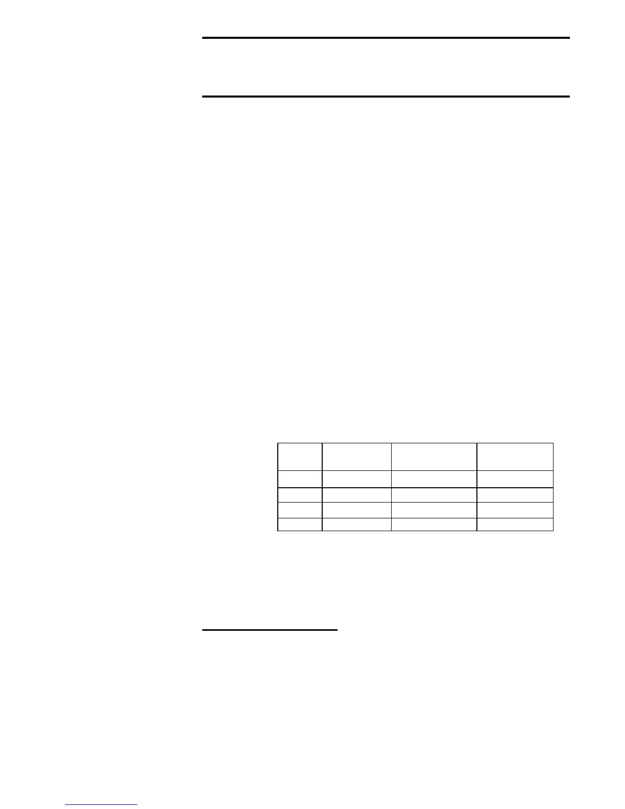
To install main power to the system (check the table below and the rating
plate on the furnace for current requirements),
• Models RA/RAD350 - Use #10 gauge stranded copper wire for
RA350 and #8 gauge for RAD350 to run a dedicated 115 volt, single
phase, line from the power source to a junction box mounted on the
wall behind the heater or as required by appropriate codes.
Models RA/RAD500 - Use #10 gauge stranded copper wire for
RA500 and RAD500 to run a dedicated 230 volt, single phase, 3 wire
with ground from the power source to a junction box mounted on the
wall behind the heater or as required by appropriate codes.
• Run the appropriate conduit from the heater to the junction box.
• Connect the black wire to L1.
• Connect the red wire to L2.
• Connect the white wire to the neutral lead.
• Connect the green wire to the ground lead.
• Install a fused manual reset, line voltage switch (eld supplied) in
this main line.
• Electrical
Ratings
A 24-volt thermostat is furnished as standard equipment.
DO NOT attempt to wire relays or other accessories to the thermostat
connections as these are not load terminals.
DO NOT install on or suspend the thermostat from the heater
DO NOT install thermostat on a cold outside wall
To install the thermostat,
• Locate the thermostat ve feet above the oor on an inside wall,
not in the path of warm or cold air currents nor in corners where air
may be pocketed
• Remove the thermostat cover
• Make sure the heat anticipator dial is set at 0.2 amps
• Connect the wires through the back of the thermostat to the R & W
terminals
• Set the ON/OFF switch on the heater electrical box to the “OFF”
position and connect the thermostat wires to the two “T” terminals
on the ignition controller.
NOTE: If servicing a
Model RA/RAD500 heater
manufactured before
1/2005, refer to wiring
diagrams on pages 54-57.
Typical wiring diagrams
for currently manufactured
heaters are on pages 50-
53.
Model
Total Current
Amperes
Minimum Circuit
Ampacity
Maximum Fuse
Size (Supply)
RA350 23 29 40
RA500 20 26 30
RAD350 34 43 50
RAD500 22 28 35