Form I-RA/D 350/500, Page 46
Fan/Blower and
Limit Controls
Locations and Temperature Settings - Model RA/RAD 350
• Fan/blower control (135°F)
• Automatic limit control (120°F)
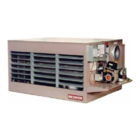
RA & RAD 350 - Access
the high temperature limit
control through the louvers
on the burner
end.
• High temperature limit
control (RA350 - 210°F;
RAD350 - 180°F;
RA & RAD 350
Limit and fan/blower controls are sub-assembled on a
mounting plate. Access control assembly by removing
the turning box door. (Cabinet parts are removed for
illustration only.)
Turning Box
End
Locations and Temperature Settings - Model RA/RAD 500
• Fan/blower control (175°F)
• Automatic limit control (RA500 - 210°F; RAD500 - 230°F;
• Single-use high temperature limit control (350°F)
• Automatic limit
control (160°F)
RA & RAD 500 - Access the limit
control through the louvers on
the turning box end of the unit.
RA & RAD 500 - Limit and
fan/blower controls are sub-
assembled on a mounting
plate. Access the control
assembly by removing the
cover underneath the burner
service tray.
Service
Tray
Function - Fan/Blower and Limit Controls, Sizes 350 and 500
The main functions of the fan/blower control are to provide:
• Delay of fan or blower operation, preventing circulation of cold air at start-up.
• Continued fan or blower operation as long as the unit temperature is above minimum setting. The
fan/blower control also provides additional safety control by keeping the fan or blower in operation
in the event that a malfunction would cause the oil burner to continue to re when the thermostat is
satised.
The circulating air high temperature limit switches are nonadjustable and automatically cycle when the
internal temperature exceeds the setpoint. For the heater to operate properly and safely, the cause for the
temperature exceeding the high limit setpoint must be corrected.
The super high temperature limit switch on the Size 350 provides redundant control and is calibrated to
open at a higher temperature than the circulating air high temperature limit switch. An interruption of the circuit
by the super high limit switch indicates a major failure caused by a malfunction of the primary safety controls
or miswiring. Before attempting to re-start the heater, the cause must be corrected and the fan/blower and
limit controls replaced.
The single-use high temperature limit switch on the Size 500 provides redundant control and is calibrated
to open at a higher temperature than the other limit switches. An interruption of the circuit by the single-use
high limit switch indicates a major failure caused by a malfunction of the primary safety controls or miswiring.
Before attempting to re-start the heater, the cause must be corrected and the fan/blower and limit controls
replaced.
For Limit Control service information, see Troubleshooting Chart No. 6