GENERAL DESCRIPTION
Page 2-11
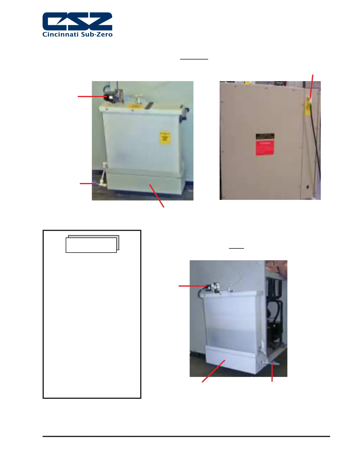
Float
Switch
Drain Valve
Pump
Water Inlet
Drain Valve
Float
Switch
Pump
Figure 8. MCB 1.2 Recirculating Water
Figure 9. MC3 Recirculating Water
MC3
MCB 1.2
For Microclimate MCB 1.2
Models the Recirculating
Water Reservoir is mounted
separately from the unit, either
on the fl oor or on a wall close
to the chamber. In addition to
the steps above, the plastic
water supply line on top of the
reservoir must be connected to
the water inlet on the Humidity
System, which is located on
the left side of the chamber.
Plug the Power Cord for the
recirculating water into a
115VAC, 60 Hz, 20 A outlet that
is separate from the chamber’s
outlet. If the chamber is rated
for the recirculating water into a
230VAC, 50Hz, 16A outlet that
is separate
NOTE
Note: CSZ is continuously upgrading the components used
in its equipment. Consequently, the physical appearance of
certain components may vary from that shown.