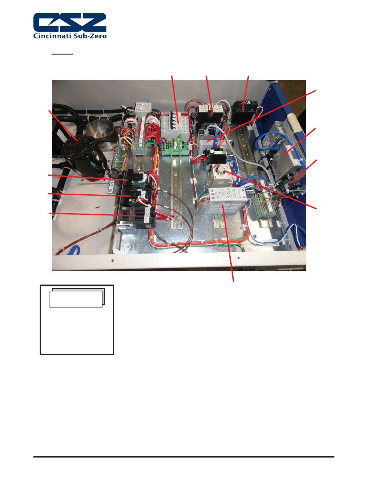
INSTALLATION
Page 4-8
Figure 7. Main Power Wiring, MC-3 with EZT-570S Controller, No Humidity
5
9
12
3
7
6
1
8
10
2
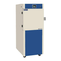
MC-3
4
1 Circuit Breakers
2 Contactor
3 Solid State Relay
4 EZT-570S Control Module
5 EZT-570S Touchscreen Unit
6 RS-232 Isolator
7 EZT Start-up Delay Timer
8 24v Power Supply
9 Chamber Limit Controller
10 Product Temperature Controller
11 Air Temperature Controller
12 Air Circulation Motor
11
Note: CSZ is continuously upgrading the components used
in its equipment. Consequently, the physical appearance of
certain components may vary from that shown.
NOTE
The number and
placement of panel
components will vary
based on options
purchased.