5. General operating rules
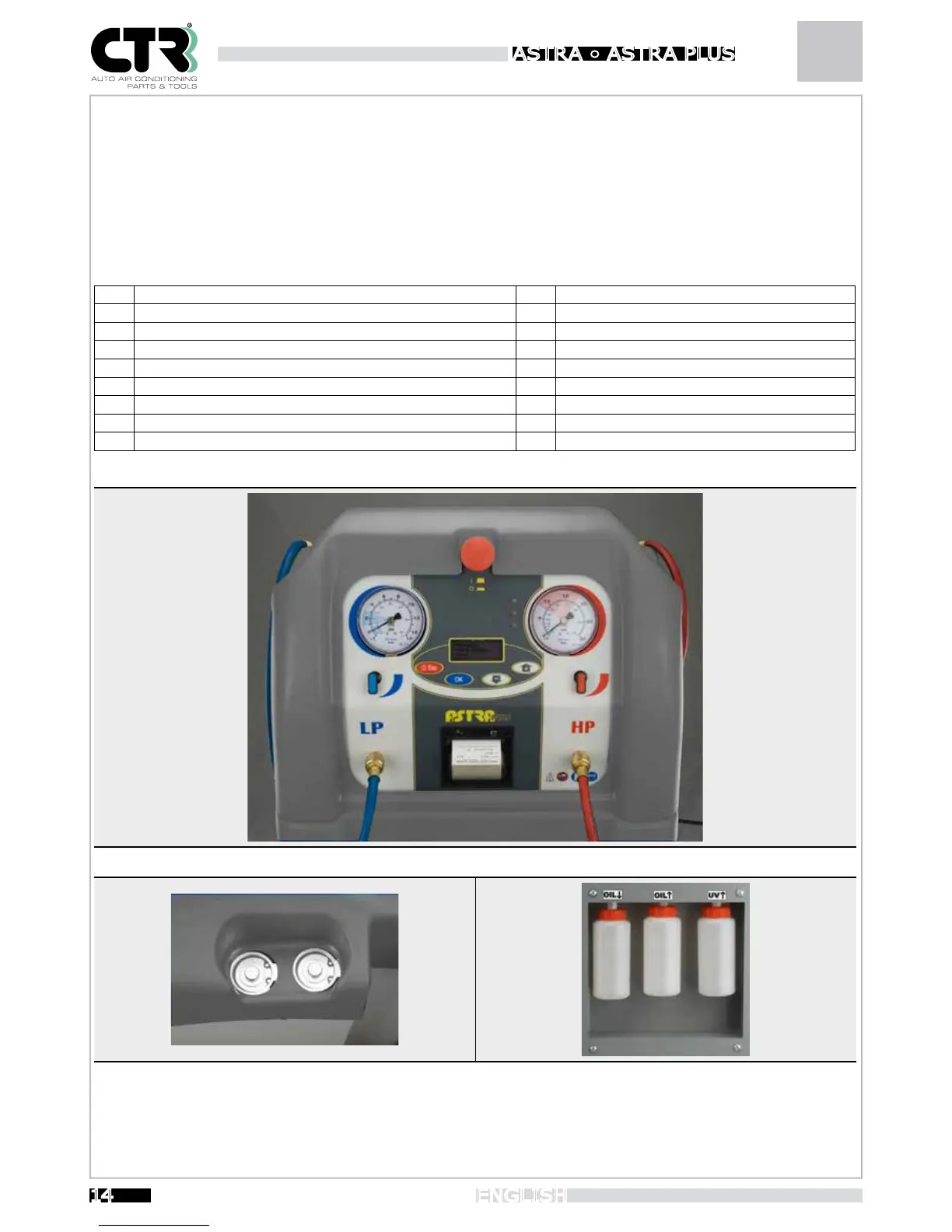
5.1 Main panel
Described below is the control panel of the unit:
Description
1 Main/emergency switch 10 HP (high pressure) valve
2 Control panel 11 Used oil discharge tank
3 ON/OFF-ESC button 12 Oil filling tank
4 OK/Enter button 13 UV tracer charge tank
5 Forward/back/plus/minus buttons 14 High pressure connection
6 Cycle function LEDs: R=recovery V=vacuum C=charge 15 Low pressure connection
7 High pressure gauge (30 bar) 16 Refrigerant filters
8 Low pressure gauge (15 bar) 17 Printer
9 LP (low pressure) valve
1
2
3
4
5
6
8
7
9 10
11 12 13
14
15
17
16