7000 High / Low Shift Kit
3
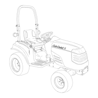
3.8. Remove the spring pin that holds the shift pin
assembly to the shaft that enters the transmis-
sion using a flat-nosed drift and a heavy ham-
mer. See Figure 3.8.
NOTE: It may be neccessary to bend the spring
pin in order to clear the spacer on the upper
mounting bolt for the hydro pump. The top end of
the spring pin is accessible through an opening
in the side of the frame.
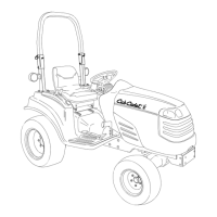
3.9. Disconnect the lift feedback rod from the hydrau-
lic lift control linkage using a 7/16” wrench.
3.10. Remove the two bolts that hold the control han-
dle bracket to the valve bracket assembly using
a 1/2” wrench and a 1/2” socket.
See Figure 3.10.
3.11. Remove the grip from the end of the hydraulic
control handle.
Figure 3.8
spring pin
shift pin
assembly
NOTE: the shift pin
assembly is visible
through an opening
in the side of the
frame.
identified in
Figure 3.4
Figure 3.10
control handle
bracket
bolts
feedback
rod
hydraulic lift
control linkage
shifter link assembly
flare fittings
3.12. Remove the control handle and control handle
bracket from the tractor.
3.13. Remove the shifter link assembly from the han-
dle bracket using a 3/4” wrench.
3.14. Place a catch pan under the hydraulic lift control
valve.
3.15. Disconnect the two steel hydraulic lines from the
two elbow flare fittings on top of the valve using
an 11/16” wrench.
NOTE: Clean the area surrounding the hydraulic
fittings before disconnecting them. It is very
important not to contaminate the hydraulic sys-
tem.
NOTE: A crow-foot wrench may ease the job of
disconnecting the flare fittings, but is not abso-
lutely essential.
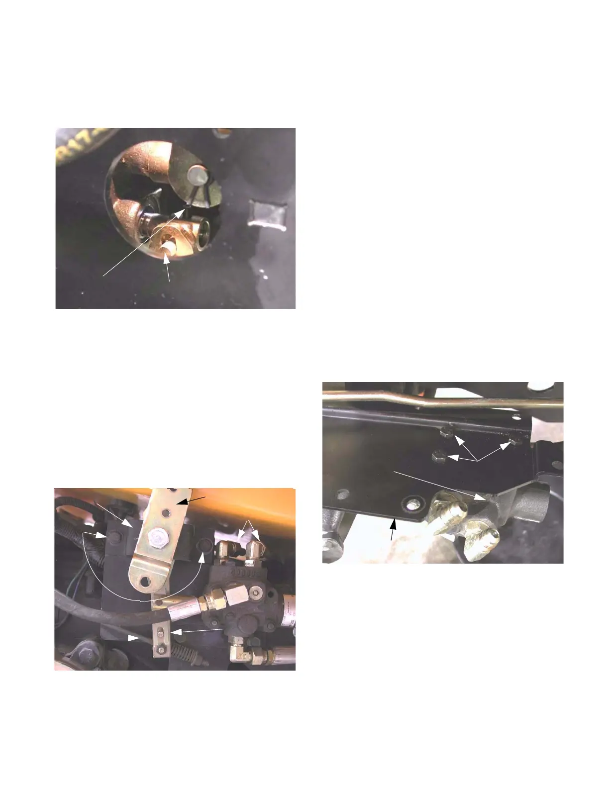
3.16. Remove the three bolts holding the valve mount-
ing bracket to the frame of the tractor using a 1/
2” wrench.
3.17. Remove the three bolts holding the valve to the
valve mounting bracket using a 7/16” wrench.
See Figure 3.17.
Figure 3.17
valve mounting bracket
bolts
hydraulic control valve

 Loading...