7000 High / Low Shift Kit
4
4. ASSEMBLY
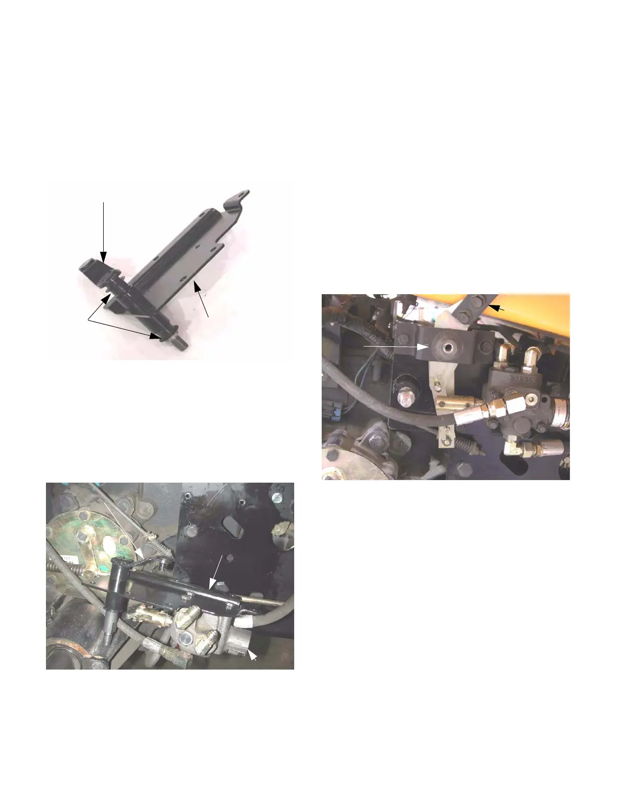
4.1. Install the plastic flange bearings in each end of
the tube on the new valve mounting bracket.
4.2. Install the shift shaft assembly in the flange bear-
ings. The arm on the shift assembly should be
on the same side of the bracket as the short side
of the tube. See Figure 4.2.
NOTE: A dry PTFE (teflon) or graphite based
lubricant will improve the service life of the
flange bearings.
4.3. Install the valve to the valve mounting bracket
using the three 1/4-20 bolts and locking nuts pre-
viously removed. See Figure 4.3.
NOTE: Apply a small quantity of thread locking
compound such as Loctite 242 (blue) to the bolts
if the locking nuts have lost friction.
4.4. Connect the steel hydraulic lines to the flare fit-
tings on top of the hydraulic pump, and snug the
flare nuts gently.
NOTE: It is easiest to connect the hydraulics
before the bracket is bolted to the frame.
4.5. Fasten the valve bracket to the frame using the
three 5/16-18 bolts previously removed.
NOTE: Apply a small quantity of thread locking
compound such as Loctite 242 (blue) to the bolts
prior to installation.
4.6. Tighten the flare nuts.
4.7. Position the hydraulic control handle and bracket
in the tractor, and connect the feedback rod to
the lever using the 1/4-20 locking nut previously
removed. See Figure 4.7.
4.8. Fasten the control handle bracket to the valve
mounting bracket using the 5/16-18 bolts and
nuts previously removed.
4.9. Apply anti-seize compound to the exposed
shoulder (double D) of the shift shaft assembly.
Install the shift lever on the shift shaft assembly
using the locking nut and flat washer supplied in
the kit.
4.10. Insert the shift handle through the outer slot in
the control console mounted on the right fender.
Bolt the handle to the bracket using the two bolts
previously removed from the old handle.
NOTE: The handle should ride against the inside
edge of the slot in the fender console. If it does
not, remove it and bend it slightly so that it does.
4.11. Install the yellow grip on the new shifter handle.
Figure 4.2
shift shaft assembly
flange
bearings
valve mounting
bracket
Figure 4.3
shift shaft assembly
hydraulic control valve
valve mounting
bracket
Figure 4.7
hydraulic
control handle
control handle
bracket

 Loading...