EasyManuals Logo

Cub Cadet Challenger 700 Operator's Manual

Cub Cadet Challenger 700
200 pages
To Next Page IconTo Next Page
To Previous Page IconTo Previous Page
Page #122 background imageLoading...
Page #122 background image
2. Install the parking brake lever boot.
3. Install the seats.
When installing the console, be sure not
to pinch the cables or wires.
Make sure that the groove at the bottom
of the parking brake lever boot and the
drive select lever boot fits securely
around the edge of the hole in the
console.
Periodic Maintenance and Adjustment 8-9
EFI system
EFI engines are completely different from
engines which use carburetors. An EFI
engine consists of an ECU, EFI-cables,
sensors, actuators, and other advanced
components.
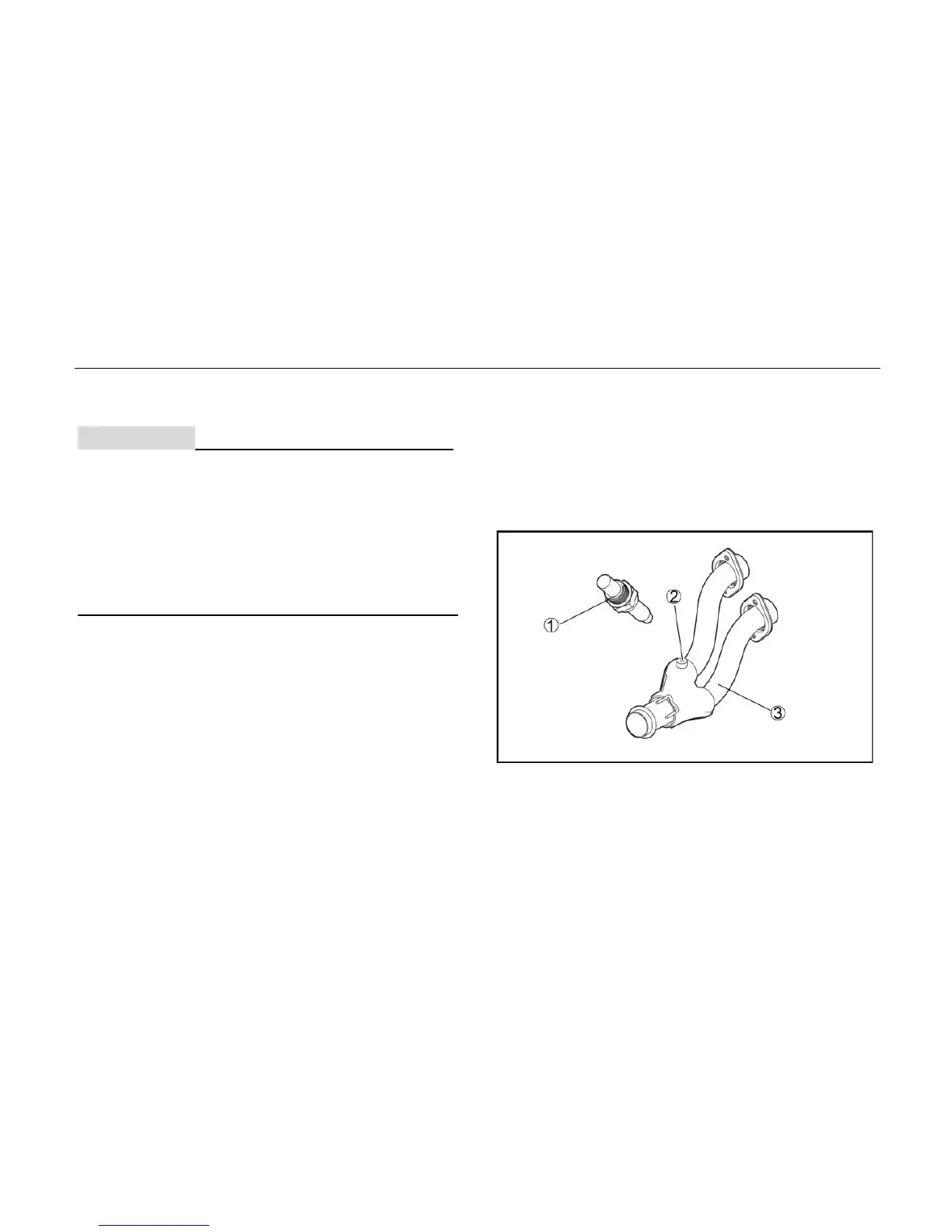
See the following pictures:
1. Oxygen sensor
2. Oxygen sensor threaded sleeve
3. Exhaust Pipe
CAUTION:

Table of Contents

Other manuals for Cub Cadet Challenger 700

Questions and Answers:

Question and Answer IconNeed help?

Do you have a question about the Cub Cadet Challenger 700 and is the answer not in the manual?

Cub Cadet Challenger 700 Specifications

General IconGeneral
BrandCub Cadet
ModelChallenger 700
CategoryUtility Vehicle
LanguageEnglish

Related product manuals