Wired Touch Panels - User Manual
15© CUE, a.s. | All Rights Reserved.
On-Wall Multisurface Models
Using Adhesive Foil
This method is typically use for glass wall installation.
www.touchone.eu | sales@cuesystem.com | support@cuesystem.com© CUE, a.s. | All rights reserved. | Published 09.11.2016
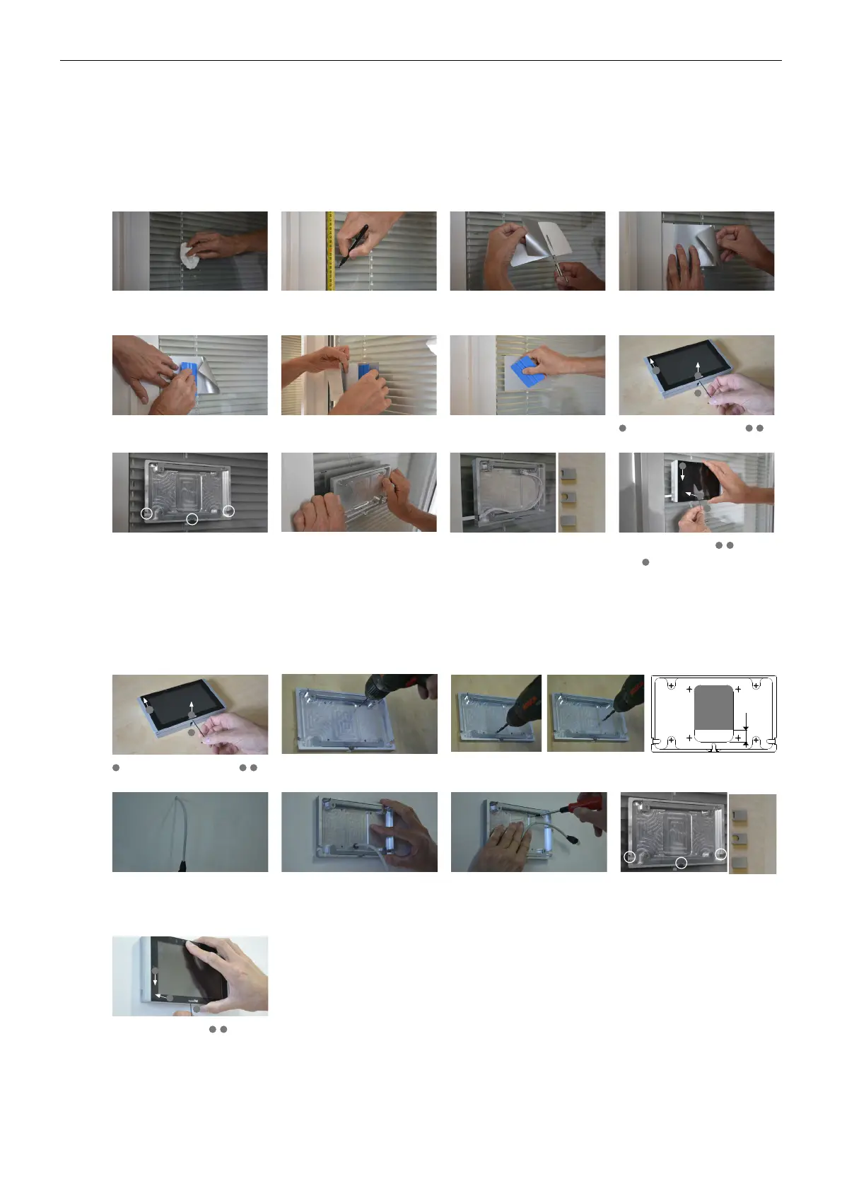
Step 2Step 1 Step 3 Step 4
Step 6Step 5 Step 7 Step 8
Step 10Step 9 Step 11 Step 12
Sign top of foil in height 1 560 mm from the floor.
It is for recommended height 1 500 mm from
floor to center of the panel.
Degrease wall (typically glass) surface with
alcohol and left it completely dry.
Partly remove protective film from adhesive foil
and cut it.
Use vertical ruler or level to adjust correct foil vertical
position. Put foil on the wall with the protective film
(not with adhesive part) to the ruler or level.
Degrease foil installed on the wall and left it
completely dry. Remove protective film from the
adhesive tape (installed on the rear side of the
back cover) and carefully attach it on the foil
Stick the adhesive part of foil using delivered
squeegee.
Partially remove the protective film and stick the
rest of the foil using a squeegee.
Squeegee lengthwise from the center outwards
with overlapping strokes.
Loosen the fixing screw using delivered Allen key -
1
and remove back cover of the panel -
2
,
3
.
Position of back cover must be oriented as
displayed above - cable bushings are left, right
and bellow side oriented.
Install cable to the selected bushing and install
appropriate cable cover. Cable length inside is
25 cm. Covers for flat and round cables as well
as for unused bushings are delivered. Covers are
fixed with adhesive tape.
Connect Ethernet cable to the panel and put
the panel on the back cover -
1
,
2
. Carefully
tighten the fixing screw to fix panel on the back
cover -
3
.
TBD
TBD
1
3
2
2
3
1
Cable length inside 25 cm
For flat
cable
For round
cable
For unused
bushing
Bushing covers
Multisurface models installation - using adhesive foil
Using Screws
www.touchone.eu | sales@cuesystem.com | support@cuesystem.com© CUE, a.s. | All rights reserved. | Published 09.11.2016
Step 2Step 1 Step 3
Step 4
Loosen the fixing screw using delivered Allen key -
1
and remove back cover of the panel -
2
,
3
.
TBD
1
3
2
Step 8
Connect Ethernet cable to the panel and put
the panel on the back cover -
1
,
2
. Carefully
tighten the fixing screw to fix panel on the back
cover -
3
.
2
3
1
Multisurface models installation - using screws
Drill four holes for screws. Use indicated
pre-drilled positions.
Drill the hole for cable. Hole diameter is 6 mm for cable without connector, 15 mm for cable with
connector. Restricted area for drilling the hole is described on the drawing.
Install cable to appropriate position on the wall
regarding restricted area described in previous
step. Recommended cable length from the wall is
25 cm. Recommended height from floor to center
of the panel is 1 500 mm.
Install cable to the cable hole and put back
cover on the wall. Position of back cover must be
oriented as displayed above - cable bushings
are left, right and bellow side oriented.
Step 5 Step 6
Fix back cover on the wall using appropriate
screws depending on the wall material.
For flat
cable
For round
cable
For unused
bushing
Bushing covers
Step 7
Install covers for unused bushings as described
above. Covers are fixed with adhesive tape.
Restricted area for cable
hole drilling
20 mm
 Loading...