6 / CULLIGAN
®
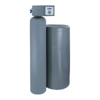
MARK 10 AUTOMATIC WATER CONDITIONER
• Place brine valve into the chamber. The top of the valve
should rest within the groove of the brine chamber.
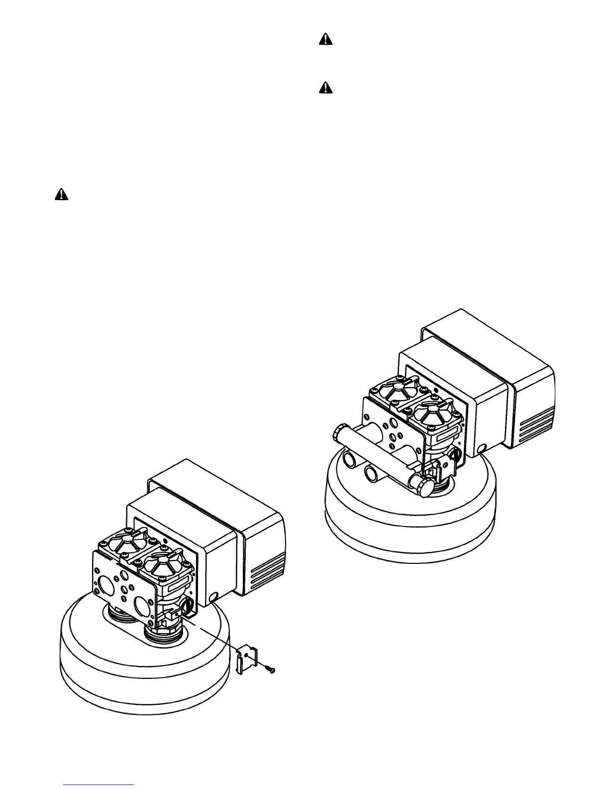
MOUNT THE CONTROL VALVE
See Fig. 2.
• Remove and discard the protective covers on the tank
couplings.
• Position the light colored tank coupling to the right. This
is the inlet side of the tank.
WARNING: FAILURE TO PROPERLY POSITION
TANK WILL RESULT IN LOSS OF MEDIA.
• Lubricate the o-rings on the tank couplings with silicon
lubricant.
• Place the control on the tank couplings and press down
firmly.
• Install the u-clamps on both sides of the control and secure
with the screws.
PLUMBING CONNECTIONS
Two methods of connecting the water softener to the plumb-
ing system are available. Shipped with each softener is a
Culligan
®
Cul-Flo-Valv
®
bypass valve, either PN
00-3314-42 or 00-3314-46. If local conditions warrant, you
may use the sweat adaptor kits, PN 00-3314-44 or
00-3314-45.
NOTICE: The Soft-Minder
®
meter cannot be used with the
sweat adaptors.
CAUTION: Close the inlet supply line and
relieve system pressure before cutting into the
plumbing! Flooding could result!
CAUTION: When making sweat connections, re-
move all plastic and rubber components which con-
tact brass or copper. Damage to these compo-
nents may result otherwise.
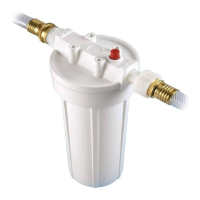
BYPASS VALVE INSTALLATION
The bypass valve connects directly to the backplate of the
valve with a pair of screws (Fig. 3). Use a long standard
screw driver to facilitate installation. Lubricate all o-rings
with silicon lubricant.
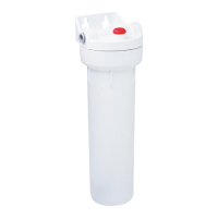
BYPASS VALVE INSTALLATION
(SOFT-MINDER
®
METER ONLY):
The Soft-Minder meter is placed between the bypass valve
and the control (Fig. 4). Make sure the meter is on the outlet
FIG. 2
FIG. 3