INSTALLATION / 7
drain line length and height limitations, and to Fig. 6.
• Remove 1/2" pipe clamp from end of drain elbow.
• Route a length of 1/2" drain line from the drain elbow to
the drain.
• Fasten the drain line to the elbow with the clamp.
• Secure the drain line to the drain to prevent its movement
during regeneration. A loop in the end of the tube will
keep it filled with water and will reduce splashing at the
beginning of each regeneration.
NOTICE: Observe all plumbing codes. most codes require
an anti-siphon device or air gap at the discharge point!
FILL THE SALT STORAGE CONTAINER
Fill the salt storage container with water until the level reaches
about 1 inch above the salt support plate. Pour salt into the
container. Fill to within a few inches of the top.
SOFT-MINDER
®
METER CONNECTIONS
To connect meter leads, proceed as follows:
• Remove the timer case by grasping the front cover and
pulling outward.
• Remove the screw from the protective cover and remove
cover.
CAUTION: Do not allow the timer case to hang
from the wires. Damage to the wires and/or termi-
nals may result.
port of the control. A pair of elongated bolts are packaged
with the meter to hold the bypass valve to the back plate of
the control. Lubricate all o-rings with silicon lubricant.
SWEAT ADAPTOR INSTALLATION
The seat adaptors use a snap ring to hold them to the backplate
of the control valve. The back plate will need to be removed
from the valve for this connection. A pair of snap ring pliers,
PN 00-5916-09, are needed for this connection.
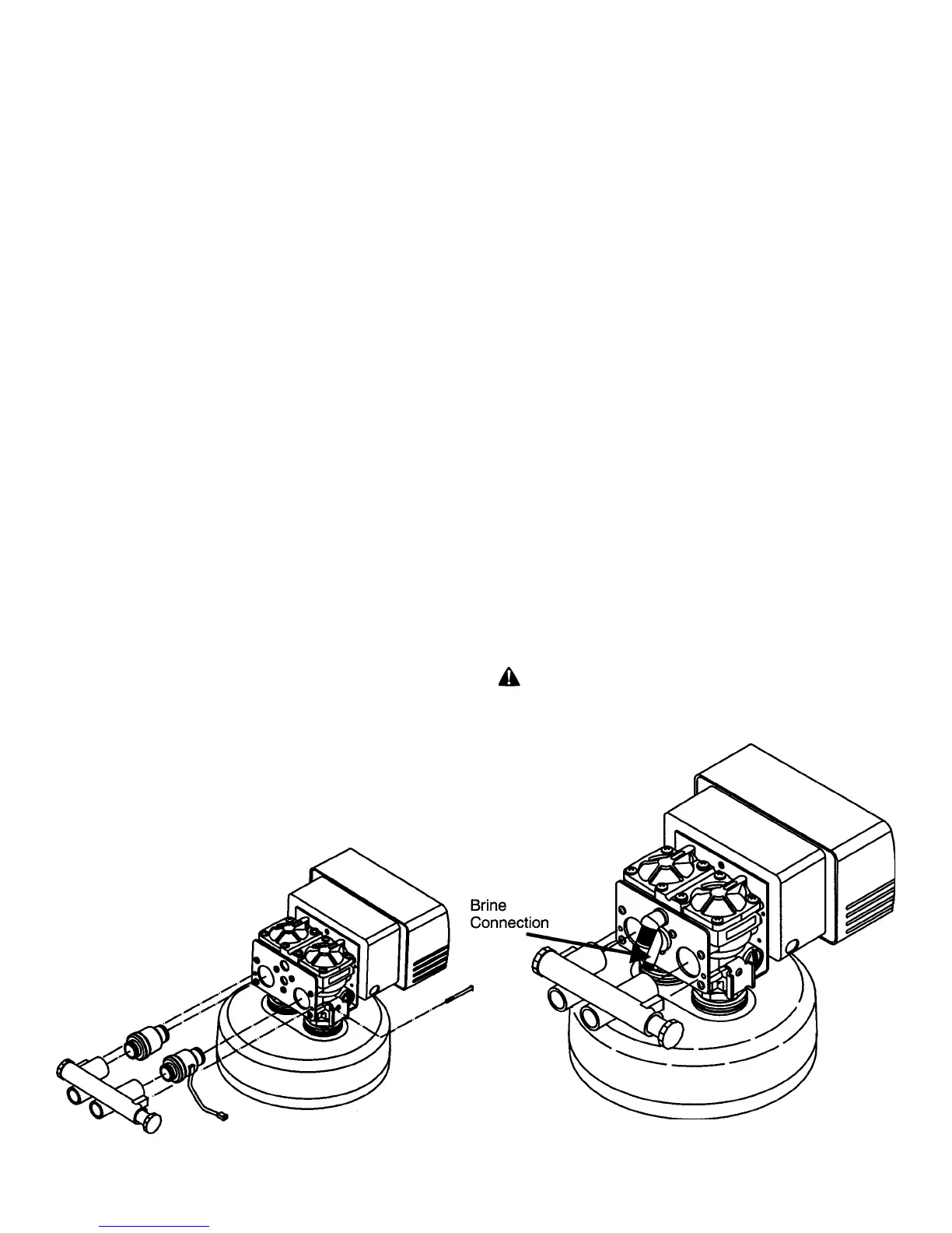
CONNECT THE BRINE LINE
Refer to Fig. 5.
• Measure a length of brine line sufficient to reach from the
brine tank to the brine fitting and then add four feet (1.3
meters). Cut both ends squarely and cleanly.
• Remove the brine valve from the brine tank and remove
the white nut and insert. Return float rod to its original
position.
• Slip the white nut over one end of the tubing and press the
plastic insert into the end of the tubing. Connect to the
brine valve and tighten nut.
• Remove white nut and insert from the brine elbow
assembly.
• Slip the white nut over one end of the tubing and press the
plastic insert into the end of the tubing. Connect to the
brine connection on the valve and tighten nut.
DRAIN LINE CONNECTION
Refer to Table 1, page 11, under the applicable tank size for
FIG. 4 FIG. 5