13
01021076
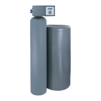
Position the Mineral Tank(s)
Determine the location for the mineral tanks(s) prior to loading, because they will be difficult to move after
the underbedding and gravel are loaded.
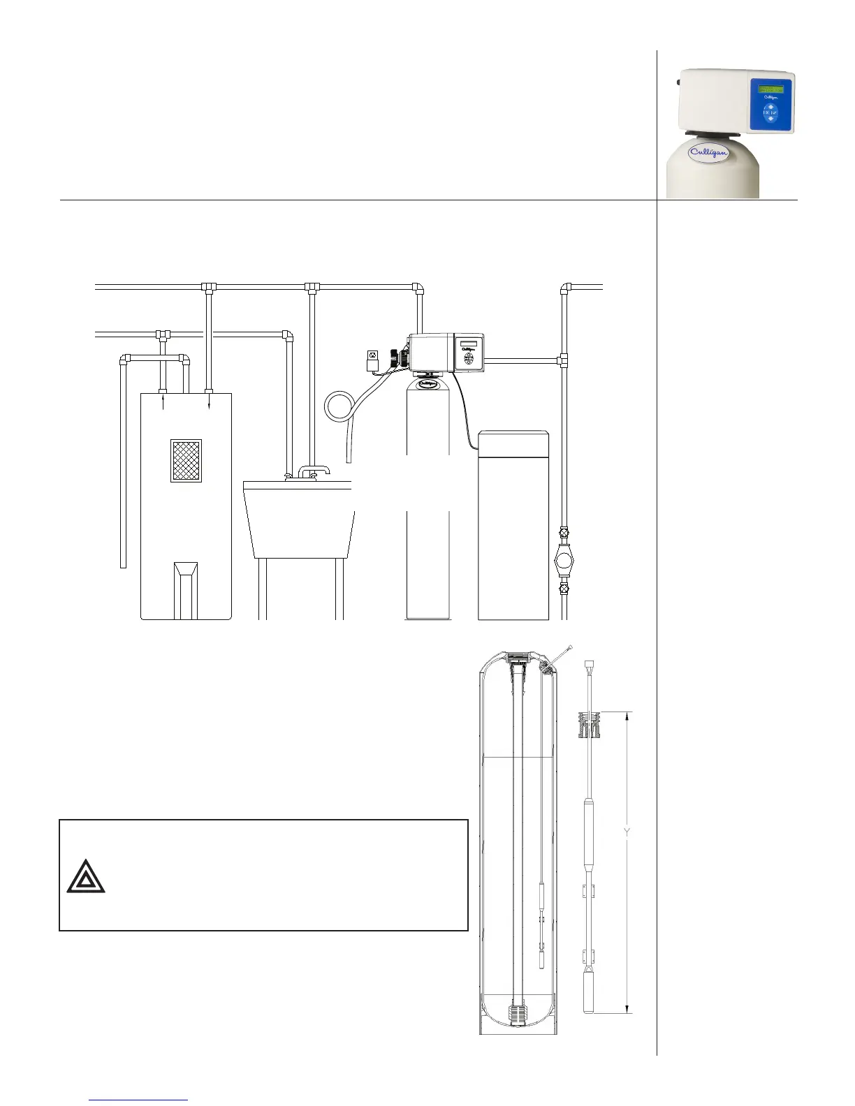
Drain Line
Hard Water In
Heater
To
Hose
Bibs
Water
Meter
or
Pump
Brine Tank
Air Gap
(2x Pipe Diameter
or 1 inch, whichever
is larger)
Figure 1. HE system placement.
Load the Tank (12" and 14" Tanks)
1. Position the tank so that the Culligan
®
logo is in the front.
2. Remove the inlet strainer.
3. Install the outlet manifold into the tank (Figure 2).
4. Cover the tops of the manifolds with a clean rag.
5. Using a large-mouth funnel, load the Culligan underbedding
through the top of the tank.
CAUTION! DO NOT allow the outlet manifold
to move when loading the media.
The manifold must remain vertical
to ensure a good seal at the gasket.
Rap the tank near the bottom with a
rubber mallet to level the sand.
6. Load the tank with the Cullex
®
ion exchange resin. Leveling is not
required.
7. Remove the funnel.
8. Install the inlet strainer making sure to thread the strainer until it
bottoms out on the tank thread. Failure to install the strainer cor-
rectly can cause the control to leak.
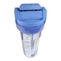
Figure 2. HE Softener tank.