Installation 17
Cat. No. 01016370
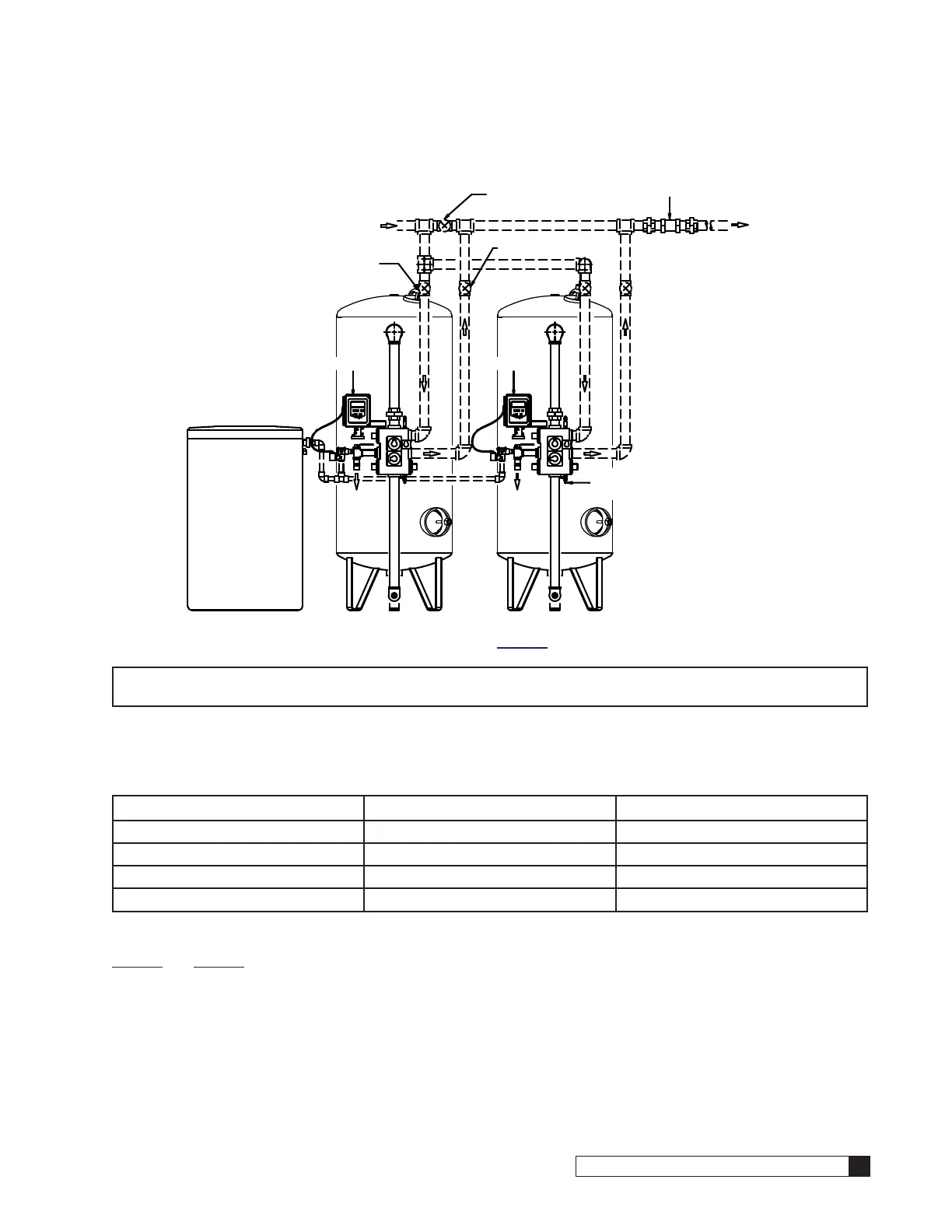
Installation of the Flow Measuring Device (Option)
BRINE TANKBRINE TANK
MVP
CONTROLLER
MVP
CONTROLLER
ISOLATION VALVE
MANUAL INLET
TO DRAIN TO DRAIN
(NORMALLY CLOSED)
MANUAL BYPASS VALVE
MANUAL OUTLET
ISOLATION VALVE
HARD WATER
SOFT WATER
SAMPLE
COCK
FLOW METER
Figure 15. Duplex Alternating Layout (See page 13 for other system piping configurations.)
NOTE Time or Aqua-Sensor initiated regenerated systems do not necessarily require the use of a flow-mea-
suring device. Therefore your system may not utilize this portion of the manual.
Two popular types of flow measuring devices can be used with the controller; paddlewheel flow sensors or the Culligan
in-line turbine meter. Please refer to the following chart for the number of meters required for your system configuration.
Table 5.
System Configuration Paddlewheel Flow Sensor Turbine Meter
Single 1 1
Duplex Parallel/Progressive Flow 2 2
Duplex Alternating 1 1
Triplex Parallel/Progressive Flow 3 3
To properly measure flow accurately, the paddlewheel flow sensor(s) must be installed with a certain amount of straight
pipe both before and after the paddlewheel flow sensor. The proper installation for these types of systems is shown on
page 18 and page 19. Turbine meters do not have the same installation requirements and therefore may be posi-
tioned immediately following the Brunermatic valve if the system is a single or parallel configuration or at any point in the
common outlet header for alternating configurations.

 Loading...


