Installation 19
Cat. No. 01016370
Position of the Flow Sensor Package
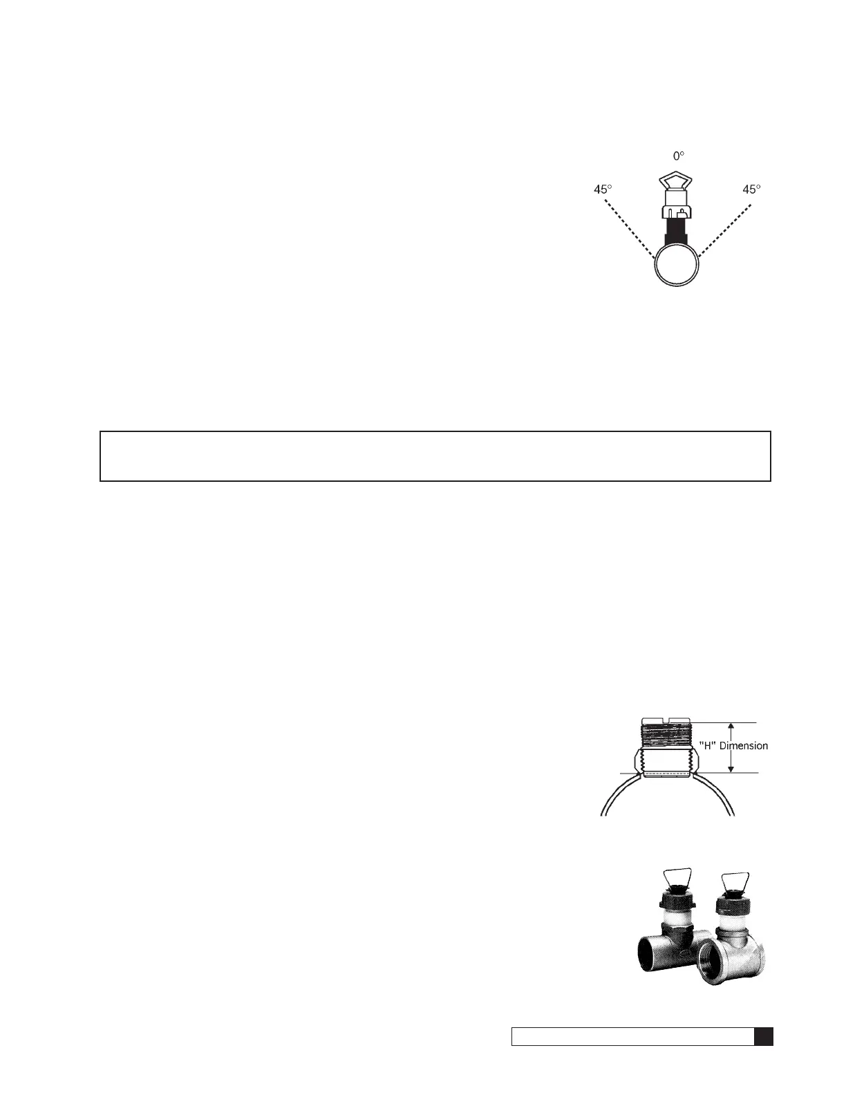
The flow sensor position is also important to the accuracy of the output signal. When
installing the flow sensor in a horizontal pipe, the optimum position of the flow sensor in
the pipe is at 0 or 180 degrees, assuming the pipe is always full of liquid and contains no
suspended solids. Air pockets or sediment in the pipe will disturb the rotation of the flow
sensor, causing inaccuracy in the output signal.
Because of certain installation requirements due to space restrictions, it may be neces-
sary to tilt the flow sensor slightly, (max. 45° angle). Excessive angles will cause bearing
drag on the flow sensor rotor at lower flow rates (see Figure 19).
On a vertical pipe run, it is preferable to locate the flow sensor where the flow is upward.
But, if downward flow is necessary, the system must be designed to prevent air/water vapor pockets from developing in
the pipe which will affect the performance of the flow sensor.
The maximum distance that the flow sensor can be located from the MVP controller is 500’. Paddlewheel type flow sen-
sors should be supported in the piping as required by local plumbing codes; typically 18” before and after each joint (in a
horizontal run of pipe).
Signet Flow Sensor Installation
NOTE Signet flow sensors must be installed as indicated. Failure to follow these instructions may result in
improper operation. Please refer to any supplemental instructions accompanying the flow sensor for
additional information.
1. Once you have located the flow sensor package and confirmed it is the correct size and material type for the
equipment at the site, proceed with installing the flow sensor mounting package.
2. You should follow good plumbing practices for all the installations. They are:
• Check the threads and make certain that they are clean and free of foreign matter.
• Fittings must be free of cracks and chips.
• Prepare threads with either a pipe sealant or Teflon tape.
• Make certain that the fittings are not cross threaded during the assembly process.
• Do not over-tighten the fittings or the threaded pipe that is being threaded into a casting or forging.
• Follow proper soldering processes as outlined in the plumbing code.
3. For each of the different types of installations, certain requirements must be followed to assure a proper installa-
tion.
a. Copper sweat tee - for use on copper tubing sizes. 1” 1-1/4”, 1-1/2”
and 2”. With the exception of the 1” copper sweat tee, all of the cop-
per tees include a plastic insert which the flow sensor will attach to.
This insert should be removed in order to properly solder the tee into
the correct position. A tag is attached to the fitting to indicate the
proper “H” dimension of the plastic insert when reassembling. This
dimension is critical to the proper calibration of the flow sensor. Note
the location of the notch to the pipe (see Figure 20 and Figure 21).
b. Threaded galvanized tee - for use on galvanized/iron pipe sizes 1”, 1-1/4”,
1-1/2” and 2”. All tees are threaded with NPT threads and have a plastic
insert to attach flow sensor. This insert is factory installed and should not
be removed. It is necessary for determining the proper location for the flow
sensor wheel when inserted into the fitting. Again this insert should not be
removed from the tee assembly (see Figure 21).
Figure 19.
Figure 20.
Figure 21.

 Loading...


