20 Culligan® CSM Series Softeners
20 Cat. No. 01016370
c. Copper brazolet - for use on copper pipe sizes 2-1/2” and 3”. The
copper brazolet should be installed by a certified welder. A hole will
need to be drilled in the pipe at the desired location as described in
this section. The hole size should be 1-7/16” and must be completely
deburred and free of any projections. Prior to welding the brazolet, the
plastic insert must be removed. A special tool is provided with each
brazolet assembly for the removal and the replacement of the plastic
insert. When the plastic insert is replaced (after the welding is com-
plete), Teflon tape should be used on the threads. There is a special
card that is attached to the insert, this card indicates the proper “H”
dimension for the insert depth when you reassemble the insert back
into the brazolet. This dimension is critical to the proper calibration of
the flow sensor. Note the location of the notch to the pipe (see Figure
22).
Figure 22.
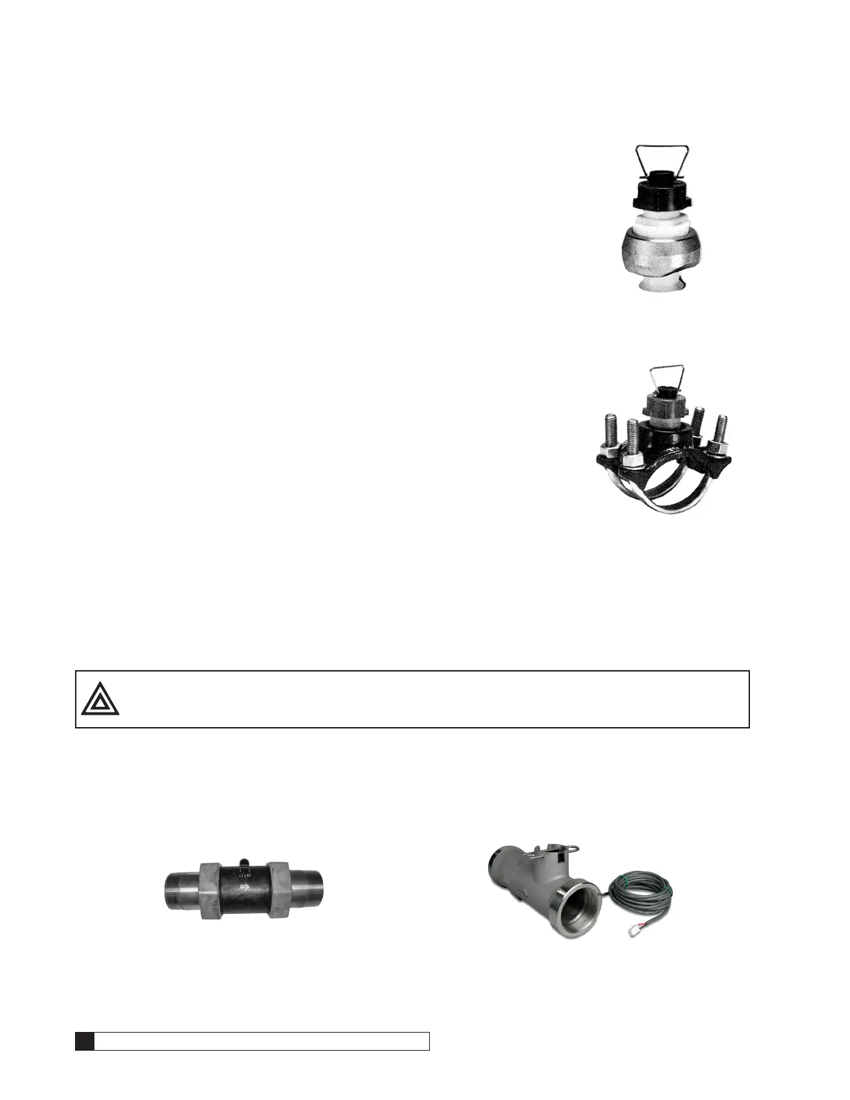
d. Iron saddle - for use on steel pipe 2”, 2-1/2” and 3”. A 1-7/16” hole
will need to be drilled in the pipe at the desired location as described
in this section. The assembly comes complete with a plastic insert
which is factory installed and should not be removed. The assembly
also comes with a rubber washer which must be installed between
the clamp and pipe. Coat the rubber washer with a silicon lubricant
and place it on the inside of the saddle and form it around the raised
groove. With the flat side of the rubber washer facing the pipe surface,
insert the plastic insert and saddle to the drilled hole. Using the saddle
clamps, tighten the saddle into place.
Figure 23.
e. PVC socket weld tee - for use on sizes 1”, 1-1/4”, 1-1/2”, 2”, 2-1/2”, 3” and 4” schedule 80 PVC pipe.
All tees are socket welded with a NPT threaded port containing a plastic insert to attach the flow
sensor. This insert is factory installed and should not be removed. It is necessary in determining the
proper location for the flow sensor wheel when inserted into the fitting. Again, this insert should not
be removed from the tee assembly. Once the flow sensor installation is completed, locate the warning
decal attached to the flow sensor. Apply the decal to a visible location near the flow sensor in the event
service is required.
CAUTION! Be certain there is no pressure in pipe BEFORE removing or installing flow sensor.
Turbine Meter Installation
Turbine meters are less sensitive to position. They can be mounted horizontally or vertically but straight runs before and
after the meter are best for accuracy. If mounted vertically, the water flow must be upward. Turbine meters however must
be supported as required by local plumbing codes; typically 18” before and after each joint (in a horizontal run of pipe).
Figure 24. Figure 25.

 Loading...


