22 Culligan® CSM Series Softeners
22 Cat. No. 01016370
Aqua-Sensor Installation (Option)
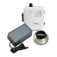
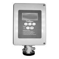
NOTE The Aqua-Sensor (Figure 30) is purchased as an optional
item. This device detects and initializes a regeneration
based upon changes in the electrical conductivity of the
resin bed. It shall also similarly detect reverse changes
during the regeneration process so as to allow for opti-
mum slow rinse times and potential water saving opera-
tion.
WARNING! For best results do not subject the Aqua-
Sensor to conditions outside the operating
parameters of the water softening system.
(See page 2).
The Aqua-Sensor device is installed through the top of the tank, usually
through a plug found in the top access opening (and using the bush-
ing provided with each Aqua-Sensor option kit). Because of it’s unique
capabilities, the Aqua-Sensor can be positioned near the upper portion of
the resin bed (providing greater reserve capacities normally required for
delayed regeneration purposes) , near the bottom of the resin bed (most
common for immediate regeneration) or anywhere
in between.
To install the Aqua-Sensor simply use the outside of the softener tank as a template for determining the length of the
Aqua-Sensor cable to be placed inside the tank. If greater system capacity is required before a regeneration signal is
sent to the controller then the Aqua-Sensor should be positioned just above the gravel sub-bed inside the softener tank.
Measure sufficient cable to allow the Aqua-Sensor to hang in place within the resin bed but not so much that the probe
would be in contact with the gravel sub-bed and potentially be damaged during the regeneration process.
Appendix C on page 96 provides detailed information about Aqua-Sensor Application Guidelines, resin bed depths,
and the estimated capacity per inch of resin bed depth at varying salt dosages.
NOTE During the backwash cycle the resin bed will be agitated which will allow the probe to settle to a level
equal to the overall length of the probe and cable. DO NOT leave more cable than necessary inside the
tank. Any excess cable should be coiled near the controller, outside of the resin tank.
Figure 30.
Figure 29.
RESIN
TANK
DISTRIBUTORS AND
GRAVEL SUB-BED
RESIN BED ZONE
AQUA-SENSOR PROBE SHOULD
BE LOCATED COMPLETELY
WITHIN THIS BED ZONE
TOP OF RESIN BED
BOTTOM OF RESIN BED
 Loading...

