Schematic 33
Cat. No. 01016370
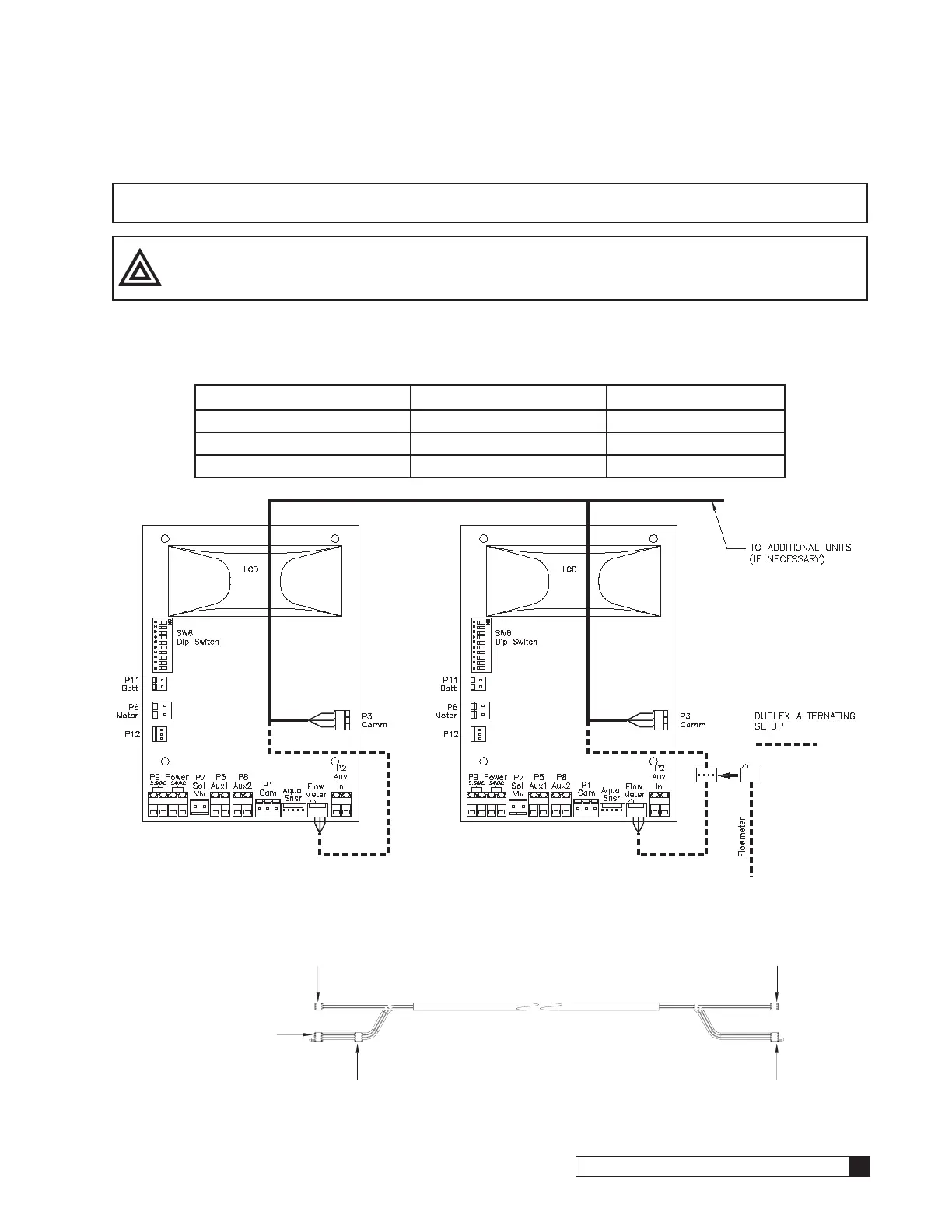
Communication Cable and Blocking Solenoids - Multiple Units
NOTE Disregard this information and proceed to flow sensor schematic (optional) information when install-
ing single tank configurations.
CAUTION! Do not connect P3 communication cable to P12 circuit board connection. Doing so will
damage the circuit board.
Multiple units will require a communication cable. Refer to the following table for the quantity and cable part number
required for your system configuration.
Table 8.
System Configuration Cable Part Number Qty. Required
Alternating Duplex 01016342 1
Duplex Parallel/Progressive 01016327 1
Triplex Parallel/Progressive 01016327 2
Figure 49.
To P3 Comm Port
on MVP Ciruit Board, #1
To Flow Meter Connection
on MVP Circuit Board.
Flow Meter Connector
(from meter).
To Flow Meter Connection
(on MVP Circuit Board).
To P3 Comm Port
on MVP Ciruit Board, #2
Figure 50. Duplex Alternating Cable (P/N 01016342)

 Loading...


