Troubleshooting 59
Cat. No. 01029343
Motorized Ball Valve Operation
When ball valves are in the “Service” position, Pilot Valve controls the flow path. When the ball valves are in the “Standby”
position, the Ball Valves with Piston #1 control the flow path.
Table 7. Ball Valve to Pilot Valve Flow Paths
Port Flow Path to/from the Ball Valve During
Ball Valve Pilot Service Standby
1 1 Pressure from the Pilot Valve
2 2 Flow to the Bottom of Piston #1 Flow from the Bottom of Piston #1
3 3 Exhaust to Drain
4 4 Exhaut through the Pilot Valve
5 5 Flow from the Top of Piston #1 Flow to the Top of Piston #1
6 6 Pressure to Ball Valve
Table 8. Ball Valve Positions
Cycle
Ball
Valve #
Indicator
Position*
1 2 3 4 5 6
Service
1 Flow Flow No Flow Flow Flow No Flow
2 Flow Flow No Flow Flow Flow No Flow
Standby
1 No Flow Flow Flow No Flow Flow Flow
2 No Flow Flow Flow No Flow Flow Flow
*Located at the top of the Ball Valve. Lines indicate which ports are connected.
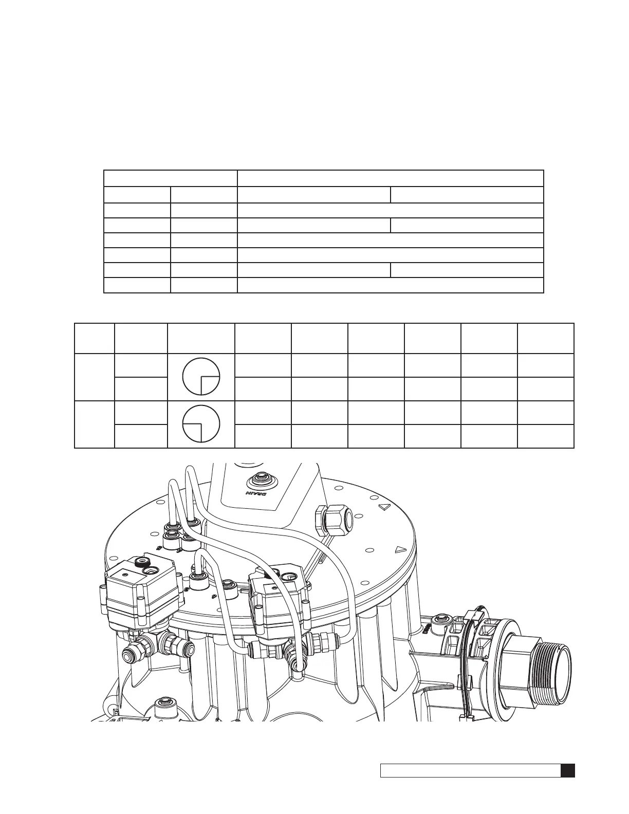
Figure 76. Ball Valve Ports (Multi-Tank Softeners Only)
3
4
Feed
5
6
3
5
2
1
Drain
1
2
4
6