Installation 15
Cat. No. 01023552
NOTE If the ground from the electrical panel or breaker box to the water meter or underground copper pipe
is tied to the copper water lines and these lines are cut during installation of the straight-through
adapter, an approved grounding strap must be used between the two lines that have been cut in order
to maintain continuity. The length of the grounding strap will depend upon the number of units being
installed. In all cases where metal pipe was originally used and is later interrupted by the straight-
through adapter to maintain proper metallic pipe bonding, an approved ground clamp c/w not less
than #6 copper conductor must be used for continuity. Check your local electrical code for the correct
clamp and cable size.
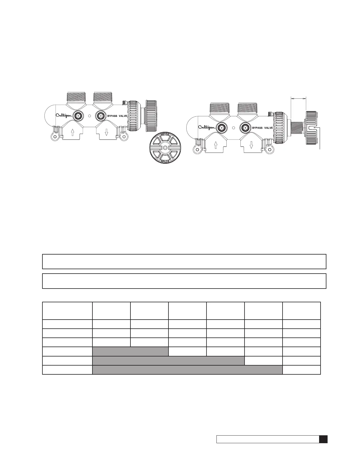
Optional Bypass Valve Installation
Refer to Figure 18 and the instructions below to connect the
meter, bypass valve, and interconnecting pipe.
1. All HE units are equipped with a Soft-Minder
®
meter.
The meter is installed on the outlet side of the control
valve. The meter body fits in the same space as the
coupling between the control valve and the bypass.
Make sure the arrow on the flow meter is pointing in
the direction of the flow.
2. The bypass valve connects directly to the control
valve with the meter and coupling and two assembly
pins. Lubricate all O-rings on the couplings/meter with
silicone lubricant.
NOTE The Low Flow Meter has a white dot on the
connection for the wire harness.
Assembly
Pins
Meter Body
Coupling
Bypass
Figure 18. Bypass valve assembly.
Optional Bypass Valve Operation
To bypass, turn the blue knob clockwise (see directional arrow on end of knob) until the knob stops as shown. DO NOT
OVERTIGHTEN! (Figure 19). To return to service, turn the blue knob counter-clockwise (see directional arrow on the end
of knob) until the knob stops as shown. DO NOT OVERTIGHTEN! (Figure 20)
Figure 19. Turn blue bypass knob clockwise.
A screwdriver shank may be
used in the slot as a lever for
extra turning force if needed.
Figure 20. Turn bypass knob counter-clockwise.
 Loading...