16 Culligan® High Efficiency 1.5 Water Softener
16 Cat. No. 01023552
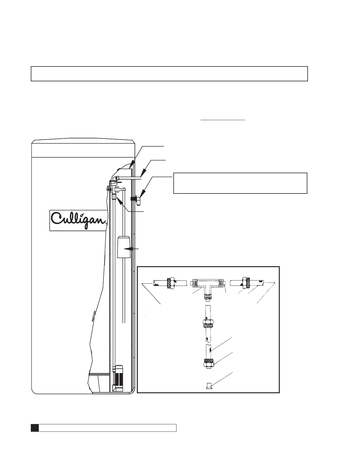
Drain Line Connection
Refer to Table 5 for drain line length and height limitations under the applicable tank size.
1. Remove 1/2” pipe clamp from the small parts pack included with the control.
2. Route a length of 1/2” drain line from the drain elbow (see Figure 17) to the drain.
3. Fasten the drain line to the elbow with the clamp.
4. Secure the drain line to prevent its movement during regeneration. When discharging into a sink, or open floor
drain, a loop in the end of the tube will keep it filled with water and will reduce splashing at the beginning of
each regeneration.
NOTE Waste connections or drain outlets shall be designed and constructed to provide for connection to the
sanitary waste system through an air gap of two pipe diameters or 1 inch, whichever is larger.
NOTE Observe all plumbing codes. Most codes require an anti-siphon device or air gap at the discharge
point. The system and installation must comply with state and local laws and regulations.
Table 5. Height of discharge above floor level operating.
Operating
Pressure
0 ft (0 m) 2 ft (0.6 m) 4 ft (1.2 m) 6 ft (1.8 m) 8 ft (2.4 m) 10 ft (3 m)
30 psi (210 kPa) 60 ft (18 m) 50 ft (15 m) 30 ft (9 m) 15 ft (5 m) Not allowable Not allowable
40 psi (279 kPa) 100 ft (30 m) 90 ft (27 m) 70 ft (21 m) 50 ft (15 m) 30 ft (9 m) 12 ft (4 m)
50 psi (349 kPa) 145 ft (41 m) 115 ft (35 m) 80 ft (24 m) 80 ft (24 m) 60 ft (18 m) 40 ft (12 m)
60 psi (419 kPa) 100 ft (30 m) 100 ft (30 m) 85 ft (26 m) 60 ft (18 m)
80 psi (559 kPa) Normal installation should not require 140 ft (43 m) 120 ft (37 m)
100 psi (699 kPa) more than 100 ft (30 m) of drain line 150 ft (46 m)
 Loading...