20 Culligan® High Efficiency 1.5 Water Softener
20 Cat. No. 01023552
Table 6. Accessory connectors and possible connections.
Part No. Description Location(s) Connection
P1025274 Strain Relief Fitting, 10 PK 1 24V Power (pre-installed)
P1025264 Strain Relief Fitting, 10 PK 1, 2, 3
Aqua-Sensor, SBT, replaces 01025274
when used with optional 2.5VAC Power
P1025277 Liquid Tight Hole Plug, 10 PK 1, 2, 3, —
P1025278 Bushing, Strain Relief, 10 PK 4, 5 HE 1.5 Twin #2
— Cord Grip, Liquid Tight 4, 5, 6 Flow Meter, Communication
To install an HE 1.5 accessory connection:
1. Remove the plastic plug from the port on the enclo-
sure, or open the port through the molded recessed
area.
2. Remove the plastic nut from the bushing attached
to the preinstalled connector cable.
3. Place the bushing with the cable through the port.
4. Tighten the nut on the interior side of the port open-
ing on the controller enclosure. See Figure 26.
5. Attach the female connector to the Smart Controller
circuit board at the appropriate location.
Nut Inside Controller Housing
Nut
Bushing
Figure 26. Connector bushing and nut position.
Installing Aqua-Sensor
1. Locate the Aqua-Sensor 2.5VAC power cord and bushing (P/N 01025264) packed in the small parts pack. The
power cord has two spade terminals on one end of the cable and a plastic female connector on the other end.
2. Disconnect power from the circuit board.
3. Remove the power cord bushing (P/N 01025274) from the outdoor enclosure (location #1 in Figure 24) by loos-
ening the nut from the 24V power cord bushing.
4. Discard the dummy connector on the 2.5VAC circuit board
pins.
5. Remove the bushing cable assembly from the enclosure.
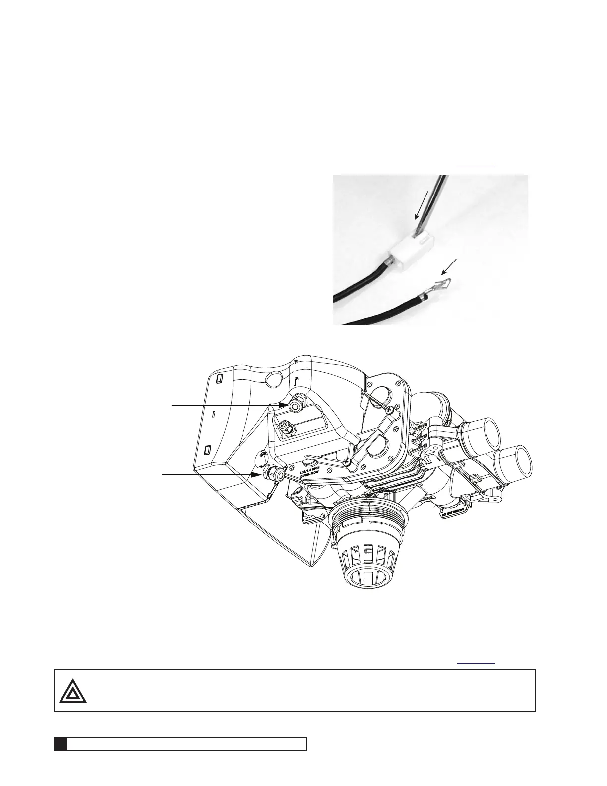
6. Press a small screwdriver into the slots on the plastic female
connector housing to remove the two metal slip-in tabs on the
24V power cord. See Figure 27.
7. Remove the P/N 01025274 bushing from the 24V power cord.
8. Insert the 24V and 2.5VAC power cords through the shared
bushing (P/N 01025264). See Figure 28.
9. Use a small screwdriver to raise the tongue on each metal tab
so it is protruding at the top. Reinstall the tabs in the housing.
Tug lightly on the cord to make sure the tab does not pull free
from the housing. See Figure 27.
Press down into
slot to release
metal tabs from
housing
Insert metal tabs
into housing with
tongue protruding
at top to ensure
secure connection
Figure 27.