Installation 21
Cat. No. 01023552
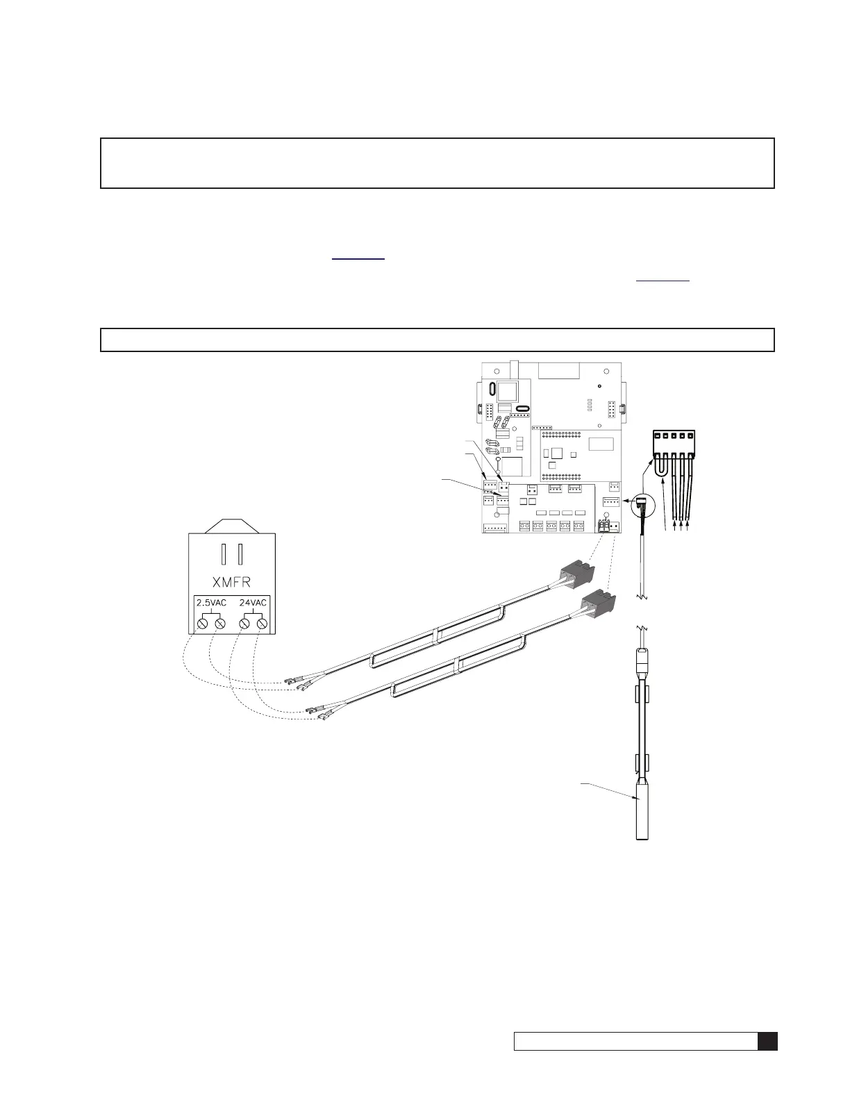
Figure 28. 24V Power and Aqua-Sensor connections on the controller.
10. Reinstall the terminal plugs on the 24V plastic connector.
11. Place the bushing with the cable through the opening and tighten the nut that is on the interior of the enclosure.
12. Plug each power connector to the appropriate pin on the Smart Controller circuit board. See Figure 29.
CAUTION! Verify wiring from the terminals to circuit board are correct before applying power to
the control. 24V power must not be applied to the 2.5 VAC terminals. Connecting 24V
to the 2.5 VAC connection on the circuit board will damage the circuit board.
NOTE The wire connectors must be connected to the circuit board properly. The wires must exit the plug-in
connector opposite of the raised white base of the circuit board connector. Failure to properly connect
any of the connectors will result in a malfunction of the circuit board operation.
13. Connect the other end of the power cord, with the spade terminals, to the two 2.5VAC terminals on the trans-
former. See Figure 29.
14. Insert the Aqua-Sensor sensor probe wire harness through the Auqa-Sensor connector opening at location #3
on the controller enclosure. See Figure 24.
15. Tighten the nut on the interior side of the port opening on the controller enclosure. See Figure 26.
16. Connect the Aqua-Sensor probe wire harness bushing to the circuit board. The Aqua-Sensor probe terminal is
labeled “Aqua-Sensor.” See Figure 29.
24V and 2.5VAC
Power Cables
Shared Connector
Aqua-Sensor Probe
Connector