Board Diagnostic
To enter the board test mode, flip all of the dip switches to the ON position. All the segments of the board will light until
either a key is depressed, an option is changed or a CAM micro switch changes position. Pressing one of the keys,
closing a micro switch or turning OFF a dip switch will cause a different segment to light as outlined in Table 5.
A balanced signal should be applied to the Aqua-Sensor
®
pin connector. This can be done with a clean Aqua-Sensor
probe and a fully regenerated bed or with the Aqua-Sensor Tester, PN 01-0079-99.
An unbalanced signal will cause the drive motor to run continuously. A balanced signal will cause the motor to stop.
This test can be used to check the integrity of the Aqua-Sensor probe. If the probe is connected to the board and
the drive motor runs continuously, the probe should be cleaned and checked.
Board Diagnostics
14 CULLIGAN
®
MARK 100 WATER SOFTENER
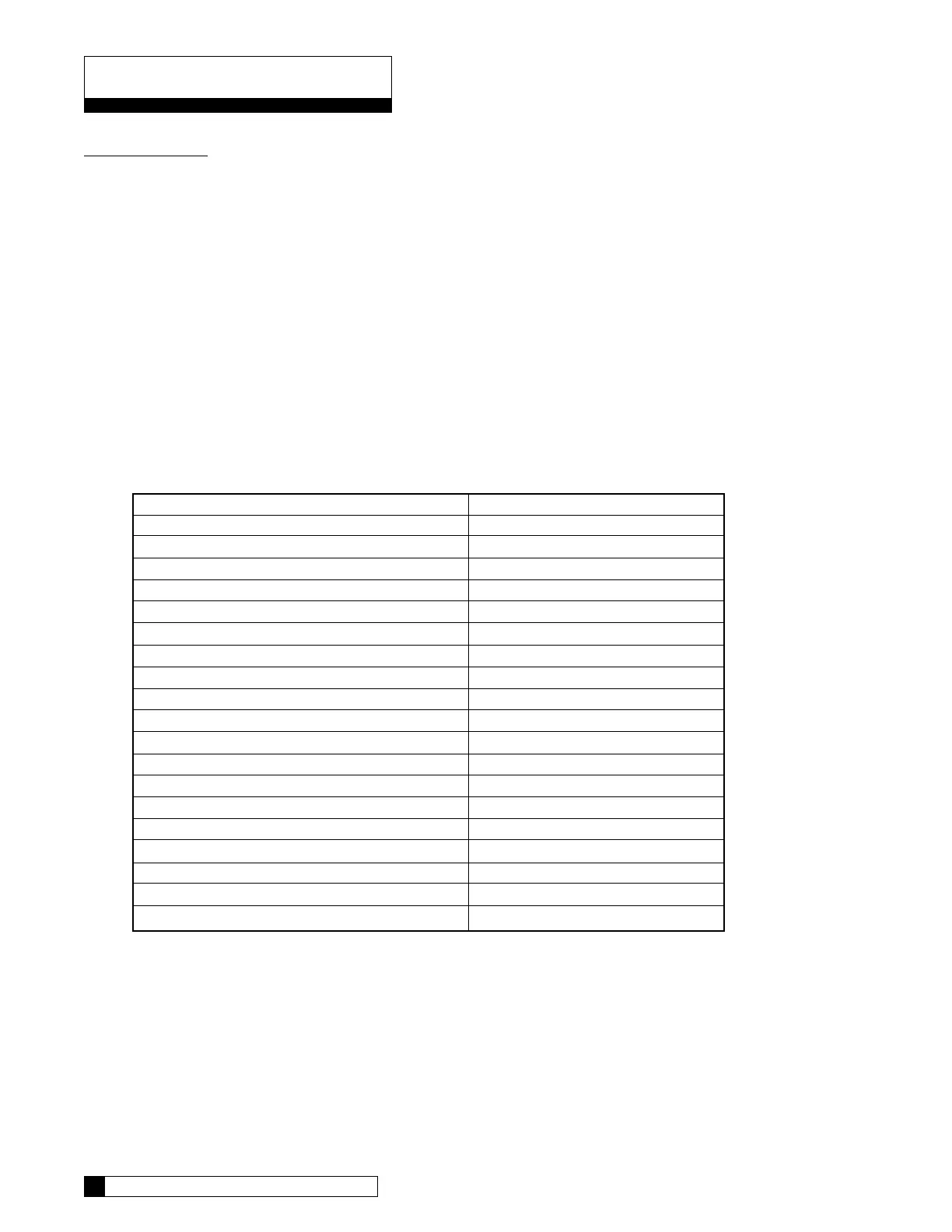
ACTION
UP KEY
DOWN KEY
REGEN KEY
STATUS KEY
CLOSED HOMING SWITCH
CLOSED PROGRAM SWITCH
FLOW METER CABLE PLUGGEDIN
AQUA-SENSOR PROBE PLUGGED IN
WATER FLOW
DIP SWITCH 1
DIP SWITCH 2
DIP SWITCH 3
DIP SWITCH 4
DIP SWITCH 5
DIP SWITCH 6
DIP SWITCH 7
DIP SWITCH 8
DIP SWITCH 9
DIP SWITCH 10
SEGMENT
1
2
3
4
5
6
7
8
9 (Fluttering)
SOFTWARE VERSION
"1111"
"2222"
"3333"
"4444"
"5555"
"6666"
"7777"
"8888"
"9999"
TABLE 5