DKC600 (U) & DKC600 (U)Y SLIDING GATE OPERATOR USER’S MANUAL
6. Connecting ----DKC600(U)
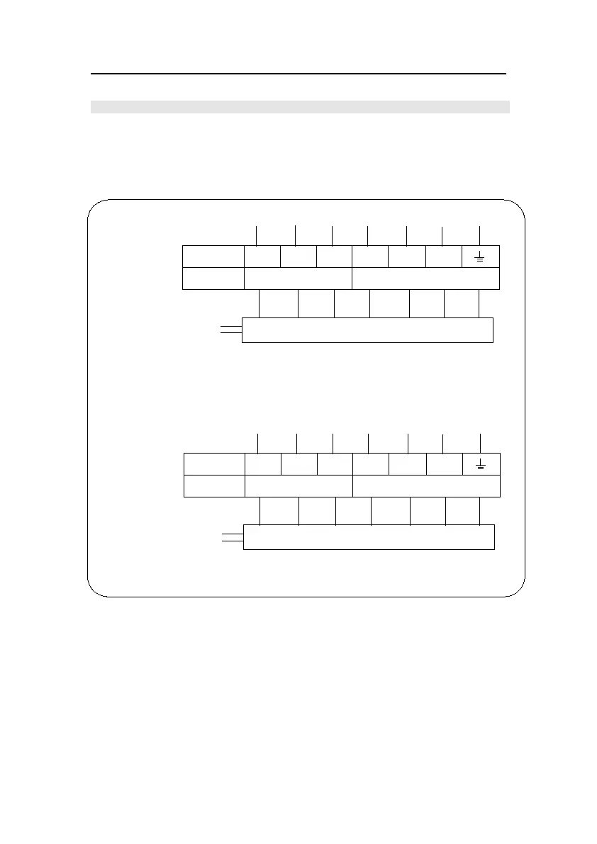
Make sure the control box power switch is OFF before connecting.
The DKC600(U) has a terminal block, Fig.12 shows the wiring of motor and limit switch, the
DKC600(U) is not equipped with control box, the control box (XF24W or XF24U) can be
purchased through your dealer.
Fig.12
RED
WHITE
RELEASE
SWITCH
CLOSED
COM
OPEN COM/U
V W
LIMIT SWITCH
MOTOR
POWER
AC110V
XF24U CONTROL BOX
BLUE
RED
WHITE
BLACK
YELLOW
AND GREEN
DKC600U GATE OPERATOR
DKC600 GATE OPERATOR
YELLOW
AND GREEN
BLACK
BROWN
BLUE
WHITE
RED
BLUE
XF24W CONTROL BOX
POWER
AC220V
MOTOR
LIMIT SWITCH
WV
COM/UOPEN
COM
CLOSED
SWITCH
RELEASE
Terminal block inside
the gate operator
Terminal block inside
the gate operator